FPGA- 序列检测器
2017-11-15 15:47
204 查看
FPGA- 序列检测器
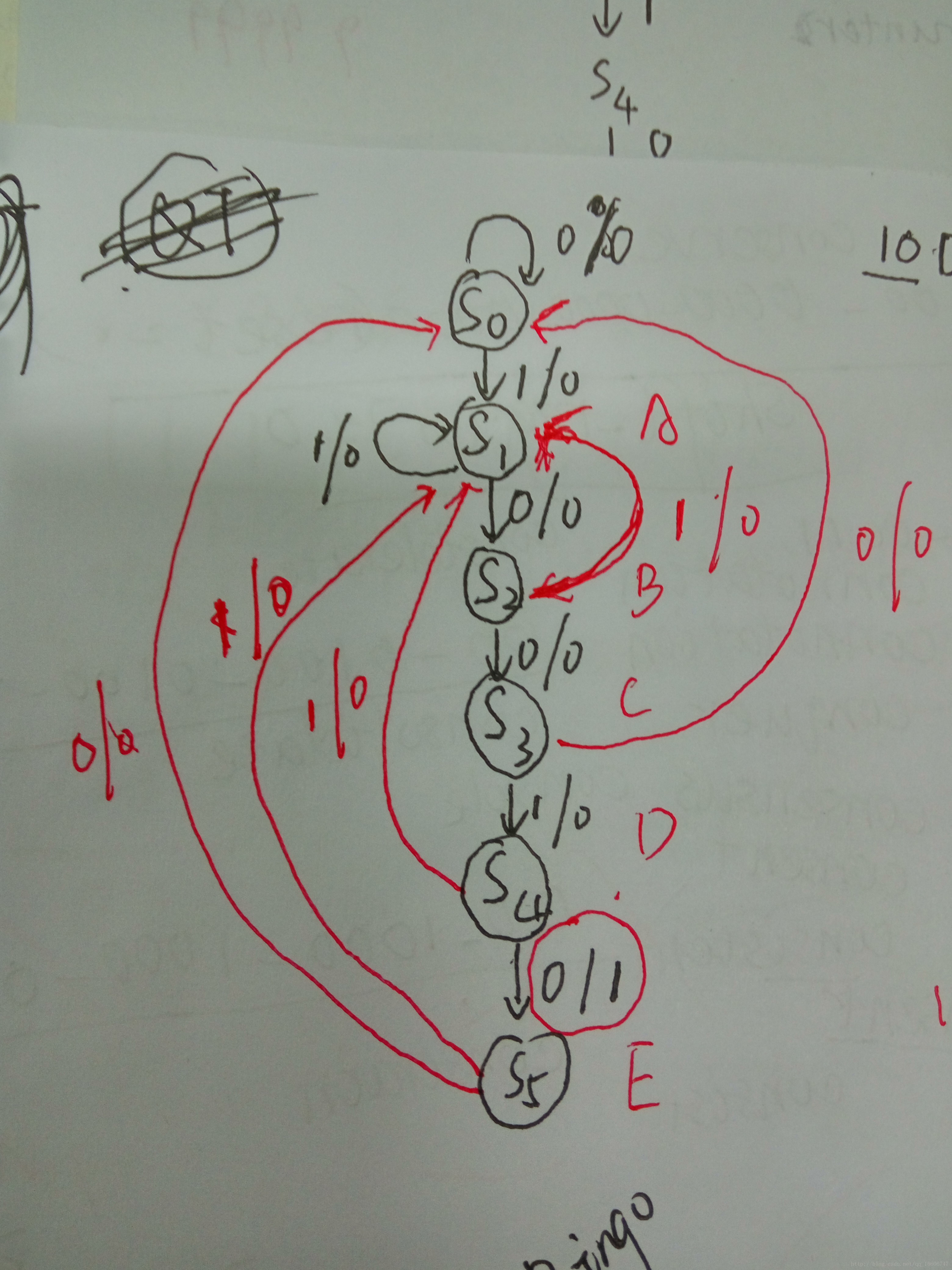
序列检测器是时序数字电路设计中经典的教学范例。下面我将用Verilog HDL语言来描述、仿真并实现它。
本次设计实现:设计一个“10010”序列的检测器。设x为数字码流输入,z为检测标记输出,高电平表示“发现指定序列”,低电平表示“没有发现指定序列”。本次设计的码流设置为data=20'b1100_1001_0000_1001_0100.其状态转换图如下面的图片。
状态转移图
代码如下:
//本设计为一个“10010”序列的检测器
module seqdet(x,z,clk,rest);
input x;
input clk;
input rest;
output reg z;

parameter s0 = 6'b000_001,
s1 = 6'b000_010,
s2 = 6'b000_100,
s3 = 6'b001_000,
s4 = 6'b010_000,
s5 = 6'b100_000;

reg [5:0] state;
always@(posedge clk or negedge rest)
if(!rest)
begin
state <= s0;
z <= 0;
end
else
case(state)
s0:begin
if(x)
begin
state <= s1;
z <= 0;
end
else
begin
state <= s0;
z <= 0;
end
end
s1:begin
if(x)
begin
state <= s1;
z <= 0;
end
else
begin
state <= s2;
z <= 0;
end
end
s2:begin
if(x)
begin
state <= s1;
z <= 0;
end
else
begin
state <= s3;
z <= 0;
end
end
s3:begin
if(x)
begin
state <= s4;
z <= 0;
end
else
begin
state <= s0;
z <= 0;
end
end
s4:begin
if(x)
begin
state <= s1;
z <= 0;
end
else
begin
state <= s5;
z <= 1;
end
end
s5:begin
if(x)
begin
state <= s1;
z <= 0;
end
else
begin
state <= s0;
z <= 0;
end
end
default: begin state <= s0;z <= 0;end
endcase
endmodule
仿真测试代码:
`timescale 1 ns/1 ns
module seqdet_tb;
wire x;
reg clk;
reg rest;
reg [23:0] data;
wire z;
assign x = data[23];
seqdet seqdet0(
.x(x),
.z(z),
.clk(clk),
.rest(rest)
);
parameter temp=20;
initial
begin
clk = 0;rest = 1;
#temp rest = 0;
#(temp*20) rest = 1;
data = 20'b1100_1001_0000_1001_0100;
#(temp*200) $stop;
end
always #(temp/2) clk = ~clk;
always@(posedge clk)
#2 data={data[22:0],data[23]};
endmodule
仿真结果:


相关文章推荐
- 基于FPGA的序列检测器
- [试验]10010序列检测器的三段式状态机实现(verilog)
- 序列检测器
- Verilog序列检测器-两例
- 序列检测器
- 10010序列检测器的三段式状态机实现(verilog)
- 三段式序列检测器的实现
- 四、FPGA之序列信号发生器
- FPGA作业3:定时产生脉冲计数序列
- fpga 状态机 检测1011序列
- 序列检测器
- FPGA之verilog第一天学习(00011101序列产生器)
- 序列检测器改编
- 每天进步一点点------基础实验_12_有限状态机 :Moore型序列检测器
- 序列检测器二
- 序列检测器1
- verilog 有限状态机的小小实例演示及仿真——序列检测器
- 6-1 Verilog Mealy状态机之序列检测器
- 【连载】 FPGA Verilog HDL 系列实例--------序列信号发生器
- 每天进步一点点------基础实验_13_有限状态机 :Mealy型序列检测器