POJ--1631
2017-08-12 15:26
387 查看
Bridging signals
Description
'Oh no, they've done it again', cries the chief designer at the Waferland chip factory. Once more the routing designers have screwed up completely, making the signals on the chip connecting the ports of two functional blocks cross each other all over the place.
At this late stage of the process, it is too expensive to redo the routing. Instead, the engineers have to bridge the signals, using the third dimension, so that no two signals cross. However, bridging is a complicated operation, and thus it is desirable to
bridge as few signals as possible. The call for a computer program that finds the maximum number of signals which may be connected on the silicon surface without crossing each other, is imminent. Bearing in mind that there may be thousands of signal ports
at the boundary of a functional block, the problem asks quite a lot of the programmer. Are you up to the task?
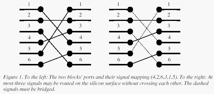
A typical situation is schematically depicted in figure 1. The ports of the two functional blocks are numbered from 1 to p, from top to bottom. The signal mapping is described by a permutation of the numbers 1 to p in the form of a list of p unique numbers
in the range 1 to p, in which the i:th number specifies which port on the right side should be connected to the i:th port on the left side.Two signals cross if and only if the straight lines connecting the two ports of each pair do.
Input
On the first line of the input, there is a single positive integer n, telling the number of test scenarios to follow. Each test scenario begins with a line containing a single positive integer p < 40000, the number of ports on the two functional blocks. Then
follow p lines, describing the signal mapping:On the i:th line is the port number of the block on the right side which should be connected to the i:th port of the block on the left side.
Output
For each test scenario, output one line containing the maximum number of signals which may be routed on the silicon surface without crossing each other.
Sample Input
Sample Output
Source
Northwestern Europe 2003
| Time Limit: 1000MS | Memory Limit: 10000K | |
| Total Submissions: 14619 | Accepted: 7909 |
'Oh no, they've done it again', cries the chief designer at the Waferland chip factory. Once more the routing designers have screwed up completely, making the signals on the chip connecting the ports of two functional blocks cross each other all over the place.
At this late stage of the process, it is too expensive to redo the routing. Instead, the engineers have to bridge the signals, using the third dimension, so that no two signals cross. However, bridging is a complicated operation, and thus it is desirable to
bridge as few signals as possible. The call for a computer program that finds the maximum number of signals which may be connected on the silicon surface without crossing each other, is imminent. Bearing in mind that there may be thousands of signal ports
at the boundary of a functional block, the problem asks quite a lot of the programmer. Are you up to the task?
A typical situation is schematically depicted in figure 1. The ports of the two functional blocks are numbered from 1 to p, from top to bottom. The signal mapping is described by a permutation of the numbers 1 to p in the form of a list of p unique numbers
in the range 1 to p, in which the i:th number specifies which port on the right side should be connected to the i:th port on the left side.Two signals cross if and only if the straight lines connecting the two ports of each pair do.
Input
On the first line of the input, there is a single positive integer n, telling the number of test scenarios to follow. Each test scenario begins with a line containing a single positive integer p < 40000, the number of ports on the two functional blocks. Then
follow p lines, describing the signal mapping:On the i:th line is the port number of the block on the right side which should be connected to the i:th port of the block on the left side.
Output
For each test scenario, output one line containing the maximum number of signals which may be routed on the silicon surface without crossing each other.
Sample Input
4
6
4
2
6
3
1
5
10
2
3
4
5
6
7
8
9
10
1
8
8
7
6
5
4
3
2
1
9
5
8
9
2
3
1
7
4
6
Sample Output
3
9
1
4
Source
Northwestern Europe 2003
#include<cstdio>
#include<algorithm>
#define maxn 55000
#define INF 0x7ffffff
using namespace std;
int a[maxn];
int dp[maxn];
int main()
{
int T;
scanf("%d",&T);
while (T--)
{
int n;
scanf("%d",&n);
for (int i=0; i<n; i++)
scanf("%d",&a[i]);
for (int i=0; i<=n; i++)dp[i]=INF;
for (int i=0; i<n; i++)
*lower_bound(dp,dp+n,a[i])=a[i];
printf("%d\n",lower_bound(dp,dp+n,INF)-dp);
}
return 0;
}

相关文章推荐
- 刷题——Bridging signals POJ - 1631
- poj 1631 简单的LIS问题
- poj 1631 最长上升子序列 nlogn
- OpenJudge/Poj 1631 Bridging signals
- POJ 1631 Bridging signals(优化的最长子序列)
- POJ1631解题报告
- POJ 1631 Bridging signals(LIS)
- poj 1631(Bridging signals LIS)nlogn
- poj 1631 Bridging signals LIS 最长非递减子序列
- zoj 1986 || poj 1631 Bridging Signals(最长上升子序列N*logN)
- Bridging signals(poj 1631)
- poj 1631 || hdu 1950 Bridging signals(动态规划:LIS)
- poj 1631 Bridging signals dp LIS
- POJ 1631 Bridging signals
- poj 1631 LIS
- POJ 1631 Bridging signals LIS(最长递增子序列) +nlogn算法+二分查找
- POJ 1631 Bridging signals(最长上升序列)
- POJ_1631_Bridging Signals_机智!/线段树
- poj-1631Bridging signals(LIS)
- POJ1631 最长上升子序列的新做法0(n)