【OpenCV】透视变换 Perspective Transformation(续)
2017-07-20 11:22
239 查看
这篇文章是我从自己的QQ(632846506)日志中移过来的。https://user.qzone.qq.com/632846506/infocenter。
透视变换的原理和矩阵求解请参见前一篇《透视变换
Perspective Transformation》。在OpenCV中也实现了透视变换的公式求解和变换函数。
求解变换公式的函数:
Mat getPerspectiveTransform(const Point2f src[], const Point2f dst[])
。
透视变换的原理和矩阵求解请参见前一篇《透视变换
Perspective Transformation》。在OpenCV中也实现了透视变换的公式求解和变换函数。
求解变换公式的函数:
Mat getPerspectiveTransform(const Point2f src[], const Point2f dst[])
。
| 输入原始图像和变换之后的图像的对应4个点,便可以得到变换矩阵。之后用求解得到的矩阵输入perspectiveTransform便可以对一组点进行变换: [cpp] view plaincopy   void perspectiveTransform(InputArray src, OutputArray dst, InputArray m) 注意这里src和dst的输入并不是图像,而是图像对应的坐标。应用前一篇的例子,做个相反的变换: [cpp] view plaincopy int main( ) { Mat img=imread("boy.png"); int img_height = img.rows; int img_width = img.cols; vector<Point2f> corners(4); corners[0] = Point2f(0,0); corners[1] = Point2f(img_width-1,0); corners[2] = Point2f(0,img_height-1); corners[3] = Point2f(img_width-1,img_height-1); vector<Point2f> corners_trans(4); corners_trans[0] = Point2f(150,250); corners_trans[1] = Point2f(771,0); corners_trans[2] = Point2f(0,img_height-1); corners_trans[3] = Point2f(650,img_height-1); Mat transform = getPerspectiveTransform(corners,corners_trans); cout<<transform<<endl; vector<Point2f> ponits, points_trans; for(int i=0;i<img_height;i++){ for(int j=0;j<img_width;j++){ ponits.push_back(Point2f(j,i)); } } perspectiveTransform( ponits, points_trans, transform); Mat img_trans = Mat::zeros(img_height,img_width,CV_8UC3); int count = 0; for(int i=0;i<img_height;i++){ uchar* p = img.ptr<uchar>(i); for(int j=0;j<img_width;j++){ int y = points_trans[count].y; int x = points_trans[count].x; uchar* t = img_trans.ptr<uchar>(y); t[x*3] = p[j*3]; t[x*3+1] = p[j*3+1]; t[x*3+2] = p[j*3+2]; count++; } } imwrite("boy_trans.png",img_trans); return 0; } 得到变换之后的图片: 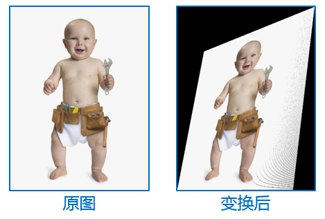 注意这种将原图变换到对应图像上的方式会有一些没有被填充的点,也就是右图中黑色的小点。解决这种问题一是用差值的方式,再一种比较简单就是不用原图的点变换后对应找新图的坐标,而是直接在新图上找反向变换原图的点。说起来有点绕口,具体见前一篇《透视变换 Perspective Transformation》的代码应该就能懂啦。 除了getPerspectiveTransform()函数,OpenCV还提供了findHomography()的函数,不是用点来找,而是直接用透视平面来找变换公式。这个函数在特征匹配的经典例子中有用到,也非常直观: [cpp] view plaincopy int main( int argc, char** argv ) { Mat img_object = imread( argv[1], IMREAD_GRAYSCALE ); Mat img_scene = imread( argv[2], IMREAD_GRAYSCALE ); if( !img_object.data || !img_scene.data ) { std::cout<< " --(!) Error reading images " << std::endl; return -1; } //-- Step 1: Detect the keypoints using SURF Detector int minHessian = 400; SurfFeatureDetector detector( minHessian ); std::vector<KeyPoint> keypoints_object, keypoints_scene; detector.detect( img_object, keypoints_object ); detector.detect( img_scene, keypoints_scene ); //-- Step 2: Calculate descriptors (feature vectors) SurfDescriptorExtractor extractor; Mat descriptors_object, descriptors_scene; extractor.compute( img_object, keypoints_object, descriptors_object ); extractor.compute( img_scene, keypoints_scene, descriptors_scene ); //-- Step 3: Matching descriptor vectors using FLANN matcher FlannBasedMatcher matcher; std::vector< DMatch > matches; matcher.match( descriptors_object, descriptors_scene, matches ); double max_dist = 0; double min_dist = 100; //-- Quick calculation of max and min distances between keypoints for( int i = 0; i < descriptors_object.rows; i++ ) { double dist = matches[i].distance; if( dist < min_dist ) min_dist = dist; if( dist > max_dist ) max_dist = dist; } printf("-- Max dist : %f \n", max_dist ); printf("-- Min dist : %f \n", min_dist ); //-- Draw only "good" matches (i.e. whose distance is less than 3*min_dist ) std::vector< DMatch > good_matches; for( int i = 0; i < descriptors_object.rows; i++ ) { if( matches[i].distance < 3*min_dist ) { good_matches.push_back( matches[i]); } } Mat img_matches; drawMatches( img_object, keypoints_object, img_scene, keypoints_scene, good_matches, img_matches, Scalar::all(-1), Scalar::all(-1), vector<char>(), DrawMatchesFlags::NOT_DRAW_SINGLE_POINTS ); //-- Localize the object from img_1 in img_2 std::vector<Point2f> obj; std::vector<Point2f> scene; for( size_t i = 0; i < good_matches.size(); i++ ) { //-- Get the keypoints from the good matches obj.push_back( keypoints_object[ good_matches[i].queryIdx ].pt ); scene.push_back( keypoints_scene[ good_matches[i].trainIdx ].pt ); } Mat H = findHomography( obj, scene, RANSAC ); //-- Get the corners from the image_1 ( the object to be "detected" ) std::vector<Point2f> obj_corners(4); obj_corners[0] = Point(0,0); obj_corners[1] = Point( img_object.cols, 0 ); obj_corners[2] = Point( img_object.cols, img_object.rows ); obj_corners[3] = Point( 0, img_object.rows ); std::vector<Point2f> scene_corners(4); perspectiveTransform( obj_corners, scene_corners, H); //-- Draw lines between the corners (the mapped object in the scene - image_2 ) Point2f offset( (float)img_object.cols, 0); line( img_matches, scene_corners[0] + offset, scene_corners[1] + offset, Scalar(0, 255, 0), 4 ); line( img_matches, scene_corners[1] + offset, scene_corners[2] + offset, Scalar( 0, 255, 0), 4 ); line( img_matches, scene_corners[2] + offset, scene_corners[3] + offset, Scalar( 0, 255, 0), 4 ); line( img_matches, scene_corners[3] + offset, scene_corners[0] + offset, Scalar( 0, 255, 0), 4 ); //-- Show detected matches imshow( "Good Matches & Object detection", img_matches ); waitKey(0); return 0; } findHomography()函数直接通过两个平面上相匹配的特征点求出变换公式,之后代码又对原图的四个边缘点进行变换,在右图上画出对应的矩形。这个图也很好地解释了所谓透视变换的“Viewing Plane”。 |

相关文章推荐
- OpenCV中二维点求取进行仿射和透视变换之后的坐标点方法
- opencv 透视变换
- Opencv之仿射变换和透视变换
- Opencv中使用Surf特征实现图像配准及对透视变换矩阵H的平移修正
- python opencv实现任意角度的透视变换实例代码
- case5 opencv中透视变换结合直线检测对图像进行校正
- OpenCV实践之路——opencv玩数独之一九宫格轮廓提取与透视变换
- opencv-第六章-图像变换-重映射、仿射变换、透视变换
- 图像的透视变换(opencv2实现)
- 对倾斜的图像进行修正——基于opencv 透视变换
- OpenCV 透视变换
- OpenCV 透视变换实例
- opencv仿射变换、透视变换
- opencv系列之一 利用透视变换实现图像的俯视图(正视图)
- opencv-ios开发笔记9 使用透视变换矫正扭曲的图片
- 【学习opencv】透视变换 Perspective Transformation
- opencv3/C++ 平面对象识别&透视变换
- Opencv——仿射变换和透视变换
- opencv仿射变换与透视变换
- 【OpenCV3图像处理】仿射变换 透视变换