CCS5.4+Proteus8的F28027实践课十三、I2C
2016-08-18 23:54
323 查看
今晚我们来学习I2C的编程,呵呵,还是老规矩,最简单的非中断回环测试。
先来总体看下寄存器结构
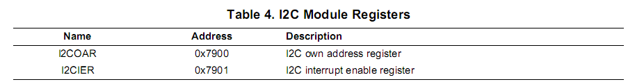
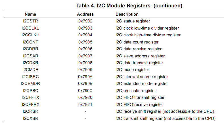
其实对于我们今晚的主题来讲,主要用到了I2COAR、I2CSTR、I2CCLKL、I2CCLKH、I2CDRR、I2CDXR、I2CMDR、I2CPSC这几个寄存器,详细的寄存器介绍大家自己下去看,我们就不浪费时间说这个了。
然后我们来理一下操作步骤:
1、使能外设I2C时钟(这步非常重要,也很容易忽略);
2、在复位状态下,设置I2C时钟PSC、I2CCLKL、I2CCLKH,还要设置地址信息和回环模式;
3、使能I2C;
4、设置I2C相关引脚;
5、编写发送和接收函数,在这里需要注意的是,TRX这位的值,当为0时,是接收模式;为1时,是发送模式;
好了,思路大概就这样,刚刚去写程序测试了一把,是OK的,我直接贴程序了
首先是I2C的初始化函数
然后是GPIO引脚设置
然后是I2C发送子程序
接着是接收子程序
最后是主函数
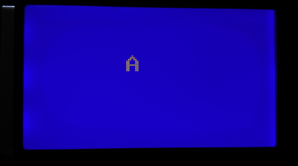
程序下载测试结果如图
那到这里,简单的I2C了解就差不多了,大家可以继续发散拓展学习,我也要洗洗睡了,最近几天睡太晚了,白天都快没状态了,不能顾此失彼,鱼和熊掌要兼得,呵呵。
F28027菜鸟交流qq群107691092
先来总体看下寄存器结构
其实对于我们今晚的主题来讲,主要用到了I2COAR、I2CSTR、I2CCLKL、I2CCLKH、I2CDRR、I2CDXR、I2CMDR、I2CPSC这几个寄存器,详细的寄存器介绍大家自己下去看,我们就不浪费时间说这个了。
然后我们来理一下操作步骤:
1、使能外设I2C时钟(这步非常重要,也很容易忽略);
2、在复位状态下,设置I2C时钟PSC、I2CCLKL、I2CCLKH,还要设置地址信息和回环模式;
3、使能I2C;
4、设置I2C相关引脚;
5、编写发送和接收函数,在这里需要注意的是,TRX这位的值,当为0时,是接收模式;为1时,是发送模式;
好了,思路大概就这样,刚刚去写程序测试了一把,是OK的,我直接贴程序了
首先是I2C的初始化函数
void InitI2C()
{
EALLOW;

SysCtrlRegs.PCLKCR0.bit.I2CAENCLK = 1;

I2caRegs.I2COAR=0x003f;  //7-bit addressing

I2caRegs.I2CMDR.bit.IRS = 0;
I2caRegs.I2CMDR.bit.DLB=1;

I2caRegs.I2CPSC.all = 5;   //  7M <= 60M/(PSC+1)  <=12M
I2caRegs.I2CCLKL = 15;
I2caRegs.I2CCLKH = 15;
I2caRegs.I2CMDR.bit.IRS = 1;

EDIS;
}
然后是GPIO引脚设置
void InitI2CGpio()
{

EALLOW;

/* Enable internal pull-up for the selected pins */
// Pull-ups can be enabled or disabled disabled by the user.
// This will enable the pullups for the specified pins.
// Comment out other unwanted lines.

GpioCtrlRegs.GPAPUD.bit.GPIO28 = 0;    // Enable pull-up for GPIO28 (SDAA)
GpioCtrlRegs.GPAPUD.bit.GPIO29 = 0;       // Enable pull-up for GPIO29 (SCLA)

//    GpioCtrlRegs.GPBPUD.bit.GPIO32 = 0;    // Enable pull-up for GPIO32 (SDAA)
//    GpioCtrlRegs.GPBPUD.bit.GPIO33 = 0;       // Enable pull-up for GPIO33 (SCLA)

/* Set qualification for selected pins to asynch only */
// This will select asynch (no qualification) for the selected pins.
// Comment out other unwanted lines.

GpioCtrlRegs.GPAQSEL2.bit.GPIO28 = 3;  // Asynch input GPIO28 (SDAA)
GpioCtrlRegs.GPAQSEL2.bit.GPIO29 = 3;  // Asynch input GPIO29 (SCLA)

//    GpioCtrlRegs.GPBQSEL1.bit.GPIO32 = 3;  // Asynch input GPIO32 (SDAA)
//  GpioCtrlRegs.GPBQSEL1.bit.GPIO33 = 3;  // Asynch input GPIO33 (SCLA)

/* Configure I2C pins using GPIO regs*/
// This specifies which of the possible GPIO pins will be I2C functional pins.
// Comment out other unwanted lines.

GpioCtrlRegs.GPAMUX2.bit.GPIO28 = 2;   // Configure GPIO28 for SDAA operation
GpioCtrlRegs.GPAMUX2.bit.GPIO29 = 2;   // Configure GPIO29 for SCLA operation

//    GpioCtrlRegs.GPBMUX1.bit.GPIO32 = 1;   // Configure GPIO32 for SDAA operation
//    GpioCtrlRegs.GPBMUX1.bit.GPIO33 = 1;   // Configure GPIO33 for SCLA operation

EDIS;
}
然后是I2C发送子程序
void I2C_WriteData(unsigned char data)
{
I2caRegs.I2CSAR = 0X003f;
I2caRegs.I2CMDR.bit.MST = 1;
I2caRegs.I2CMDR.bit.TRX = 1;
I2caRegs.I2CMDR.bit.STT = 1;
I2caRegs.I2CMDR.bit.STP = 1;

while(I2caRegs.I2CSTR.bit.BB!=1);
I2caRegs.I2CDXR = data;
}
接着是接收子程序
unsigned char I2C_ReadData()
{
unsigned char data;
I2caRegs.I2CMDR.bit.TRX = 0;
I2caRegs.I2CMDR.bit.STT = 1;
I2caRegs.I2CMDR.bit.STP = 1;
while(I2caRegs.I2CSTR.bit.RRDY!=1);
data = I2caRegs.I2CDRR&0x00ff;
return data;
}
最后是主函数
void main(void)
{

// Step 1. Initialize System Control:
// PLL, WatchDog, enable Peripheral Clocks
// This example function is found in the DSP2802x_SysCtrl.c file.
InitSysCtrl();

// Step 2. Initalize GPIO:
// This example function is found in the DSP2802x_Gpio.c file and
// illustrates how to set the GPIO to it's default state.
InitGpio();

// Step 3. Clear all interrupts and initialize PIE vector table:
// Disable CPU interrupts
DINT;

// Initialize PIE control registers to their default state.
// The default state is all PIE interrupts disabled and flags
// are cleared.
// This function is found in the DSP2802x_PieCtrl.c file.
InitPieCtrl();

// Disable CPU interrupts and clear all CPU interrupt flags:
IER = 0x0000;
IFR = 0x0000;

// Initialize the PIE vector table with pointers to the shell Interrupt
// Service Routines (ISR).
// This will populate the entire table, even if the interrupt
// is not used in this example.  This is useful for debug purposes.
// The shell ISR routines are found in DSP2802x_DefaultIsr.c.
// This function is found in DSP2802x_PieVect.c.
InitPieVectTable();

// Step 4. Initialize all the Device Peripherals:
// This function is found in DSP2802x_InitPeripherals.c
// InitPeripherals(); // Not required for this example

// Step 5. User specific code:

InitI2C();
InitI2CGpio();
InitLCD12864();

WRITECMD_LCD12864(0x93);

I2C_WriteData('A');
WRITEDATA_LCD12864(I2C_ReadData());
while(1);
}
程序下载测试结果如图
那到这里,简单的I2C了解就差不多了,大家可以继续发散拓展学习,我也要洗洗睡了,最近几天睡太晚了,白天都快没状态了,不能顾此失彼,鱼和熊掌要兼得,呵呵。
F28027菜鸟交流qq群107691092

相关文章推荐
- CCS5.4+Proteus8的F28027实践课二、定时器0控制LED流水灯
- CCS5.4+Proteus8的F28027实践课十、SPI
- CCS5.4+Proteus8的F28027实践课十二、SCI
- CCS5.4+Proteus8的F28027实践课六、实验板焊接调试(12864部分)
- CCS5.4+Proteus8的F28027实践课七、ADC
- CCS5.4+Proteus8的F28027实践课五、实验板焊接调试
- CCS5.4+Proteus8的F28027实践课九、比较器
- CCS5.4+Proteus8的F28027实践课一、延时函数控制LED流水灯
- CCS5.4+Proteus8的F28027实践课四、并行驱动LCD12864
- CCS5.4+Proteus8的F28027实践课十一、串行12864
- 微软云计算介绍与实践(实践之十三)
- 日语语法实践篇十三——新编日语第一册第十四课之总结篇
- 【DSP开发】利用CCS5.4开发基于DSP6455的JPEG2000图像解压缩过程
- Sql实践怎么规范sql数据和五大约束.十三
- Redis进阶实践之十三 Redis的Redis-trib.rb脚本文件使用详解
- RESTful服务最佳实践——(十三)
- ccs5.4安装说明
- HAWQ取代传统数仓实践(十三)——事实表技术之周期快照
- Linux实践工程师学习笔记十三
- 笔记_并发编程实践_十三