ISE数字设计入门体验
2016-04-20 12:46
369 查看
一个典型的使用ISE设计的数字系统一般包含以下步骤:
工程的建立
模块设计
设计综合和查看综合结果
工程设计仿真
分频器的设计
用户约束的添加和设计是实现
布局布线结果查看
设计下载到FPGA芯片
PROM文件的生成和下载到PROM中
源文件类型
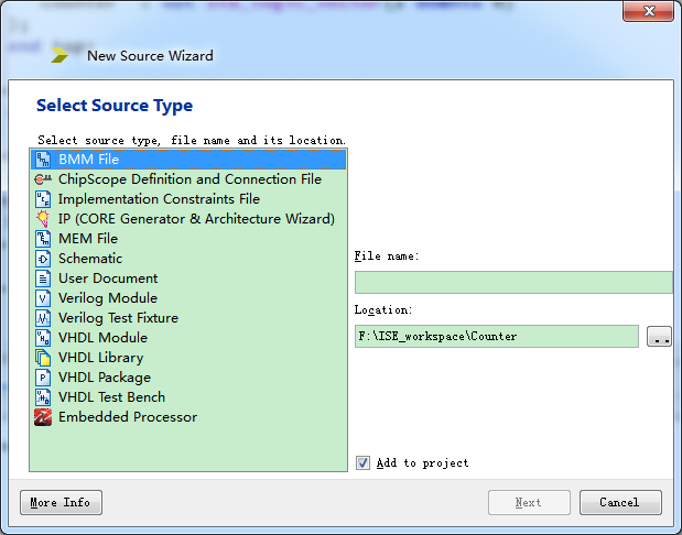
如上图,在添加新的源文件时候,会根据我们目的的不同选择文件类型。这些文件类型从上往下依次是:
块存储器映像文件
在线逻辑分析仪Chipscope定义和连接文件
实现约束文件
IP生成向导
存储器文件
原理图文件
用户文档文件
Verilog模块模板文件
Verilog测试平台模板文件
VHDL模块模板文件
VHDL库模板文件
VHDL包模板文件
VHDL测试平台模板文件
片上系统设计向导
three-bit-counter
新建一个VHDL模块模板文件之后,根据我们要设计的3位计数器设计逻辑:library IEEE; use IEEE.STD_LOGIC_1164.ALL; use IEEE.STD_LOGIC_ARITH.ALL; use IEEE.STD_LOGIC_UNSIGNED.ALL; -- Uncomment the following library declaration if using -- arithmetic functions with Signed or Unsigned values --use IEEE.NUMERIC_STD.ALL; -- Uncomment the following library declaration if instantiating -- any Xilinx primitives in this code. --library UNISIM; --use UNISIM.VComponents.all; entity top is //此处添加端口声明语句 port( clk : in std_logic; rst : in std_logic; counter : out std_logic_vector(2 downto 0) ); end top; architecture Behavioral of top is //内部信号量声明语句 signal counter_tmp : std_logic_vector(2 downto 0); begin //添加信号连接 counter<=counter_tmp; process(clk,rst) //3bit 8进制计数器模块 begin if(rst='0')then counter_tmp<="000"; elsif rising_edge(clk)then counter_tmp<=counter_tmp+1; end if; end process; end Behavioral;
设计的综合
ISE综合工具在对设计的综合过程中,主要执行以下三个步骤:语法检查过程,检查设计文件语法是否有错误
编译过程,翻译和优化HDL代码,将其转化为综合工具可以识别的元件序列。
映射过程,将这些可以识别的元件序列转化为可识别的目标技术的基本原件。
在ISEden主页面的处理子串口的Synthesis工具可以完成:
查看RTL原理图
查看技术原理图
检查语法
产生综合后仿真模型
进行行为仿真
在ISE主页面的Design区域选中Simulation选项.选中已经添加的逻辑模块右键添加测试文件.
LIBRARY ieee;
USE ieee.std_logic_1164.ALL;

-- Uncomment the following library declaration if using
-- arithmetic functions with Signed or Unsigned values
--USE ieee.numeric_std.ALL;

ENTITY test IS
END test;

ARCHITECTURE behavior OF test IS

-- Component Declaration for the Unit Under Test (UUT)

COMPONENT top
PORT(
clk : IN  std_logic;
rst : IN  std_logic;
counter : OUT  std_logic_vector(2 downto 0)
);
END COMPONENT;

--Inputs
signal clk : std_logic := '0';
signal rst : std_logic := '0';

--Outputs
signal counter : std_logic_vector(2 downto 0);

-- Clock period definitions
constant clk_period : time := 10 ns;

BEGIN

-- Instantiate the Unit Under Test (UUT)
uut: top PORT MAP (
clk => clk,
rst => rst,
counter => counter
);

//添加rst信号
process
begin
rst<='0';
wait for 100 ns;
rst<='1';
wait for 1 ms;
end process;

//生成clk信号
process
begin
clk<='0';
wait for 20 ns;
clk<='1';
wait for 20 ns;
end process;
END;
完成之后点击子任务区域的SImulate Behavioral Model,手动Zoom Out测试。
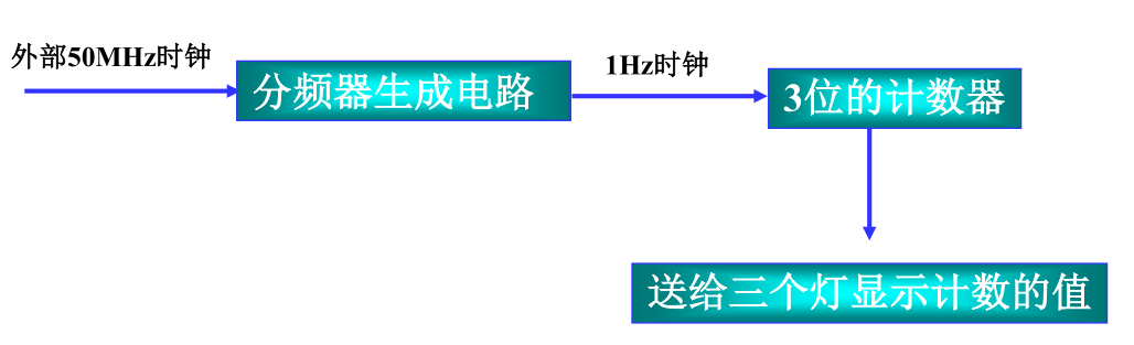
为了在硬件上看到灯的变化所反映的计数器工作状态,需要在top.vhd文件添加分频时钟代码。

相关文章推荐
- ISE数字设计入门体验
- javascript Date format(js日期格式化)
- Linq专题之创建Linq查询表达式
- .NET中获取指定文件夹下所有文件的全路径
- ABAP 创建动态内表<二>
- Zabbix 监控 Mysql 状态
- 基于Xilinx的Synthesize
- 一张图系列——为什么在DllMain里面创建了线程并Wait会卡死
- 基于Xilinx的Synthesize
- 利用session做国际化引起的old区内存爆满及修复方法
- 《sort命令的k选项大讨论》-linux命令五分钟系列之二十七
- sdut 2886 Weighted Median 结构体
- Simple, Piso, Icofoam等不可压求解器
- 1025. PAT Ranking (25)
- verilog过程块与赋值
- verilog过程块与赋值
- 主外键关联取出主键时报错[org.hibernate.LazyInitializationException] could not initialize proxy - no Session
- 发放订单以便挑库时,点击立即执行,系统自动触发请求“挑库选择列表生成”出现错误
- SQL Server 存储过程
- 如何发布一个Python命令行工具