dx11学习笔记-2.用DX画一个三角形
2016-02-13 21:08
417 查看
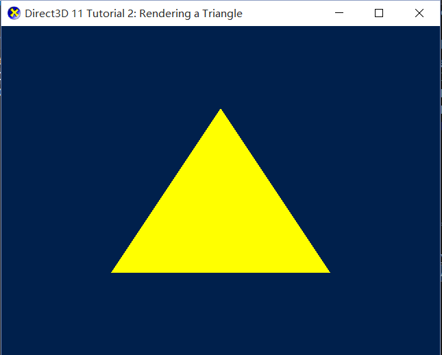
上一篇所介绍的流程是每个DX程序初始化的必需代码,运行代码可以得到一个空窗口。下面我们就开始在这个窗口上画点东西。正如学编程语言都是从hello world开始,学图形学一般都是从画三角形开始,之前学OPENGL是这样。而MS的官方教程中,Tutorial02就渲染了一个三角形。
ID3D11VertexShader* g_pVertexShader = NULL;
ID3D11PixelShader* g_pPixelShader = NULL;
ID3D11InputLayout* g_pVertexLayout = NULL;
ID3D11Buffer* g_pVertexBuffer = NULL;
从DX10开始,固定管线被完全移除,取而代之的是各种着色器。最基本的两种着色器,顶点着色器和像素着色器,是渲染一个图形所必备的。
顶点着色器,顾名思义,是对于用户定义的顶点进行变换操作,是渲染管线的入口;像素着色器则是对顶点所划出的区域,进行逐像素操作。
如果程序中只包含这两种着色器,那么像素着色器的输入,将直接来自于顶点着色器的输出。
顶点:vertex,不同于点point。它包含了更多信息,其中最基本的,也是必需的信息,就是顶点位置。所以我们定义一个顶点结构体,先把最基本的位置信息作为其内部成员。
struct Vertex
{ XMFLOAT3 pos;};
XM-XNA Math库,DX11中应用的数学库。在dx之前的版本中,用的是D3DXVECTOR3,和XMFLOAT3所代表的结构相同。
[b]1、创建并设置顶点缓存[/b]
输入顶点着色器的,需要是一块顶点缓存。dx11中若要创建顶点缓存,需要告知缓存的描述信息(D3D11_BUFFER_DESC),缓存的填充数据(D3D11_SUBRESOURCE_DATA)。
缓存描述信息中描述了该缓存的用途(BIND VERTEX),该缓存的大小(sizeof(Vertex)*顶点数量);
缓存的填充数据,就是将我们定义的顶点数组赋给其pSysMem成员完成数据绑定。
最后调用device的CreateBuffer方法,将以上二者和我们想得到的g_pVertexBuffer 地址传入。
创建成功后,context调用IASetVertexBuffers方法来设置顶点缓存。
此外,还需要设置顶点的拓扑结构,context调用IASetPrimitiveTopology方法。
所谓拓扑结构就是几何物体与其自身相连接的固有属性。
代码示例:
[b]2、创建着色器,完成输入装配[/b]
一般着色器的创建流程就两步:1、编译着色器代码片;2、根据编译得到的缓存数据创建着色器并保存。
而顶点着色器作为渲染管线的入口,还承担着接收原始输入信息的任务。所以在创建完着色器之后,我们还需要完成输入装配(Input layout)。也就是告诉顶点着色器我们输入数据的组织形式,这样着色器才知道该怎样调用输入的一堆数据。
编译步骤,需要指明着色器文件路径,着色器的入口函数名称,着色器解释模型。
代码示例:
[b]3、渲染[/b]
在每一帧都需要设置着色器并调用context的draw方法。
我们只需要在上一篇的Present方法之前,加入如下代码:
[b]4、清理[/b]
由于新增了四个变量,因此在清理时也要Release掉。
同样需要注意是从子对象到父对象,以与创建顺序相反的顺序释放。
[b]5、编写第一个着色器[/b]
虽然排第五个,但这个当然需要在第一个做啦~
由于我们在这个简单例子中不涉及顶点变换,所以顶点着色器并没干什么,它接收了用户传入的顶点位置信息后原样输出即可。同样,像素着色器只要把顶点所构成的图元所覆盖的像素一个个填充上我们需要的颜色即可。这里我们用黄色来填充。
注意函数名“VS”和“PS”对应着上面创建着色器时传入的着色器入口函数名。
语义(Semantic)
着色器采用HLSL语法, 和c++区别不大,除了它具有“语义”(Semantic)这种说法。什么是语义?下面代码中函数参数列表之后跟的的SV_POSITION、SV_TARGET可不是什么返回值类型,它只是对于返回值做出了功能说明。那么这个说明除了对使用者阅读代码时起到了帮助之外,还有什么用处呢?
当然有用处,因为DX就和使用者一样,也通过我们指定的语义来识别这些原本只是float4、matrix类型的普通变量,让它们有了指定的作用。当我们指定一个变量的语义时,Shader程序以Semantics为标记,实现变量数据从CPU到GPU的绑定。
转自http://blog.csdn.net/soilwork/article/details/1568463
从类型上来看,Semantics可以分为vertex/pixel semantics和普通变量semantics两种。
对于标记了vertex/pixel semantics值的变量来说,顶点会自动把vertex shader输入顶点或输出数据中相应的值绑定到变量上。
比如:
vs_main( float4 pos : Position, our float3 oColor : COLOR0){…}
Shader会自动把输入顶点中的位置信息绑定到pos变量上,此外
ps_main( float3 diffColor : COLOR0){…}
则会把vertex shader的输出颜色COLOR0绑定到diffColor变量。
对于普通变量semantics来说,则主要用来与外部数据进行绑定。
着色器文件Tutorial02.fx的代码如下:
基本流程
新增变量ID3D11VertexShader* g_pVertexShader = NULL;
ID3D11PixelShader* g_pPixelShader = NULL;
ID3D11InputLayout* g_pVertexLayout = NULL;
ID3D11Buffer* g_pVertexBuffer = NULL;
从DX10开始,固定管线被完全移除,取而代之的是各种着色器。最基本的两种着色器,顶点着色器和像素着色器,是渲染一个图形所必备的。
顶点着色器,顾名思义,是对于用户定义的顶点进行变换操作,是渲染管线的入口;像素着色器则是对顶点所划出的区域,进行逐像素操作。
如果程序中只包含这两种着色器,那么像素着色器的输入,将直接来自于顶点着色器的输出。
顶点:vertex,不同于点point。它包含了更多信息,其中最基本的,也是必需的信息,就是顶点位置。所以我们定义一个顶点结构体,先把最基本的位置信息作为其内部成员。
struct Vertex
{ XMFLOAT3 pos;};
XM-XNA Math库,DX11中应用的数学库。在dx之前的版本中,用的是D3DXVECTOR3,和XMFLOAT3所代表的结构相同。
[b]1、创建并设置顶点缓存[/b]
输入顶点着色器的,需要是一块顶点缓存。dx11中若要创建顶点缓存,需要告知缓存的描述信息(D3D11_BUFFER_DESC),缓存的填充数据(D3D11_SUBRESOURCE_DATA)。
缓存描述信息中描述了该缓存的用途(BIND VERTEX),该缓存的大小(sizeof(Vertex)*顶点数量);
缓存的填充数据,就是将我们定义的顶点数组赋给其pSysMem成员完成数据绑定。
最后调用device的CreateBuffer方法,将以上二者和我们想得到的g_pVertexBuffer 地址传入。
创建成功后,context调用IASetVertexBuffers方法来设置顶点缓存。
此外,还需要设置顶点的拓扑结构,context调用IASetPrimitiveTopology方法。
所谓拓扑结构就是几何物体与其自身相连接的固有属性。
代码示例:
//InitDevice函数
//新增代码
//缓存信息描述
D3D11_BUFFER_DESC bd;
ZeroMemory( &bd, sizeof(bd) );
bd.Usage = D3D11_USAGE_DEFAULT;
bd.ByteWidth = sizeof( Vertex ) * 3;
bd.BindFlags = D3D11_BIND_VERTEX_BUFFER;
bd.CPUAccessFlags = 0;
//缓存填充数据
D3D11_SUBRESOURCE_DATA InitData;
ZeroMemory( &InitData, sizeof(InitData) );
InitData.pSysMem = vertices;
//缓存创建
hr = g_pd3dDevice->CreateBuffer( &bd, &InitData, &g_pVertexBuffer );

// 设置顶点缓存
UINT stride = sizeof( SimpleVertex );
UINT offset = 0;
g_pImmediateContext->IASetVertexBuffers( 0, 1, &g_pVertexBuffer, &stride, &offset );

// 设置顶点的拓扑组织结构(三角形列表、三角形扇、三角形条带…)
g_pImmediateContext->IASetPrimitiveTopology( D3D11_PRIMITIVE_TOPOLOGY_TRIANGLELIST );
[b]2、创建着色器,完成输入装配[/b]
一般着色器的创建流程就两步:1、编译着色器代码片;2、根据编译得到的缓存数据创建着色器并保存。
而顶点着色器作为渲染管线的入口,还承担着接收原始输入信息的任务。所以在创建完着色器之后,我们还需要完成输入装配(Input layout)。也就是告诉顶点着色器我们输入数据的组织形式,这样着色器才知道该怎样调用输入的一堆数据。
编译步骤,需要指明着色器文件路径,着色器的入口函数名称,着色器解释模型。
代码示例:
//CompileShaderFromFile函数
HRESULT CompileShaderFromFile( WCHAR* szFileName, LPCSTR szEntryPoint, LPCSTR szShaderModel, ID3DBlob** ppBlobOut )
{
HRESULT hr = S_OK;
//D3DCOMPILE_ENABLE_STRICTNESS:禁止过时的语法
DWORD dwShaderFlags = D3DCOMPILE_ENABLE_STRICTNESS;
#if defined( DEBUG ) || defined( _DEBUG )
dwShaderFlags |= D3DCOMPILE_DEBUG;//编译着色器时加入调试信息
#endif

ID3DBlob* pErrorBlob;
hr = D3DX11CompileFromFile( szFileName, NULL, NULL, szEntryPoint, szShaderModel,
dwShaderFlags, 0, NULL, ppBlobOut, &pErrorBlob, NULL );
if( FAILED(hr) )
{
if( pErrorBlob != NULL )
OutputDebugStringA( (char*)pErrorBlob->GetBufferPointer() );
if( pErrorBlob ) pErrorBlob->Release();
return hr;
}
if( pErrorBlob ) pErrorBlob->Release();

return S_OK;
}

// InitDevice函数
// 新增代码
ID3DBlob* pVSBlob = NULL;
// 编译vertex shader代码文件
hr = CompileShaderFromFile( L"Tutorial02.fx", "VS", "vs_4_0", &pVSBlob );
if( FAILED( hr ) )
{
// 处理错误...
return hr;
}

// 创建 vertex shader
hr = g_pd3dDevice->CreateVertexShader( pVSBlob->GetBufferPointer(), pVSBlob->GetBufferSize(), NULL, &g_pVertexShader );
if( FAILED( hr ) )
{
pVSBlob->Release();
return hr;
}

// 编译 pixel shader代码文件
ID3DBlob* pPSBlob = NULL;
hr = CompileShaderFromFile( L"Tutorial02.fx", "PS", "ps_4_0", &pPSBlob );
if( FAILED( hr ) )
{
// 处理错误...
return hr;
}

// 创建 pixel shader
hr = g_pd3dDevice->CreatePixelShader( pPSBlob->GetBufferPointer(), pPSBlob->GetBufferSize(), NULL, &g_pPixelShader );
pPSBlob->Release();
if( FAILED( hr ) )
return hr;

// 定义input layout
D3D11_INPUT_ELEMENT_DESC layout[] =
{
{ "POSITION", 0, DXGI_FORMAT_R32G32B32_FLOAT, 0, 0, D3D11_INPUT_PER_VERTEX_DATA, 0 },
};
// 此处numElements=1
UINT numElements = ARRAYSIZE( layout );

// 创建 input layout
hr = g_pd3dDevice->CreateInputLayout( layout, numElements, pVSBlob->GetBufferPointer(),
pVSBlob->GetBufferSize(), &g_pVertexLayout );
pVSBlob->Release();
if( FAILED( hr ) )
return hr;

// 设置 input layout
g_pImmediateContext->IASetInputLayout( g_pVertexLayout );[b]3、渲染[/b]
在每一帧都需要设置着色器并调用context的draw方法。
我们只需要在上一篇的Present方法之前,加入如下代码:
// Render a triangle
g_pImmediateContext->VSSetShader( g_pVertexShader, NULL, 0 );
g_pImmediateContext->PSSetShader( g_pPixelShader, NULL, 0 );
g_pImmediateContext->Draw( 3, 0 );
[b]4、清理[/b]
由于新增了四个变量,因此在清理时也要Release掉。
同样需要注意是从子对象到父对象,以与创建顺序相反的顺序释放。
if( g_pVertexBuffer ) g_pVertexBuffer->Release();
if( g_pVertexLayout ) g_pVertexLayout->Release();
if( g_pVertexShader ) g_pVertexShader->Release();
if( g_pPixelShader ) g_pPixelShader->Release();
[b]5、编写第一个着色器[/b]
虽然排第五个,但这个当然需要在第一个做啦~
由于我们在这个简单例子中不涉及顶点变换,所以顶点着色器并没干什么,它接收了用户传入的顶点位置信息后原样输出即可。同样,像素着色器只要把顶点所构成的图元所覆盖的像素一个个填充上我们需要的颜色即可。这里我们用黄色来填充。
注意函数名“VS”和“PS”对应着上面创建着色器时传入的着色器入口函数名。
语义(Semantic)
着色器采用HLSL语法, 和c++区别不大,除了它具有“语义”(Semantic)这种说法。什么是语义?下面代码中函数参数列表之后跟的的SV_POSITION、SV_TARGET可不是什么返回值类型,它只是对于返回值做出了功能说明。那么这个说明除了对使用者阅读代码时起到了帮助之外,还有什么用处呢?
当然有用处,因为DX就和使用者一样,也通过我们指定的语义来识别这些原本只是float4、matrix类型的普通变量,让它们有了指定的作用。当我们指定一个变量的语义时,Shader程序以Semantics为标记,实现变量数据从CPU到GPU的绑定。
转自http://blog.csdn.net/soilwork/article/details/1568463
从类型上来看,Semantics可以分为vertex/pixel semantics和普通变量semantics两种。
对于标记了vertex/pixel semantics值的变量来说,顶点会自动把vertex shader输入顶点或输出数据中相应的值绑定到变量上。
比如:
vs_main( float4 pos : Position, our float3 oColor : COLOR0){…}
Shader会自动把输入顶点中的位置信息绑定到pos变量上,此外
ps_main( float3 diffColor : COLOR0){…}
则会把vertex shader的输出颜色COLOR0绑定到diffColor变量。
对于普通变量semantics来说,则主要用来与外部数据进行绑定。
着色器文件Tutorial02.fx的代码如下:
//--------------------------------------------------------------------------------------
// Vertex Shader
//--------------------------------------------------------------------------------------
float4 VS( float4 Pos : POSITION ) : SV_POSITION
{
return Pos;
}
//--------------------------------------------------------------------------------------
// Pixel Shader
//--------------------------------------------------------------------------------------
float4 PS( float4 Pos : SV_POSITION ) : SV_Target
{
return float4( 1.0f, 1.0f, 0.0f, 1.0f );    // Yellow, with Alpha = 1
}
完整代码
除了以上的新内容,其余内容与上一篇相同。//--------------------------------------------------------------------------------------
// File: Tutorial02.cpp
//
// This application displays a triangle using Direct3D 11
//
// Copyright (c) Microsoft Corporation. All rights reserved.
//--------------------------------------------------------------------------------------
#include <windows.h>
#include <d3d11.h>
#include <d3dx11.h>
#include <d3dcompiler.h>
#include <xnamath.h>
#include "resource.h"
//--------------------------------------------------------------------------------------
// Structures
//--------------------------------------------------------------------------------------
struct SimpleVertex
{
XMFLOAT3 Pos;
};
//--------------------------------------------------------------------------------------
// Global Variables
//--------------------------------------------------------------------------------------
HINSTANCE g_hInst = NULL;
HWND g_hWnd = NULL;
D3D_DRIVER_TYPE g_driverType = D3D_DRIVER_TYPE_NULL;
D3D_FEATURE_LEVEL g_featureLevel = D3D_FEATURE_LEVEL_11_0;
ID3D11Device* g_pd3dDevice = NULL;
ID3D11DeviceContext* g_pImmediateContext = NULL;
IDXGISwapChain* g_pSwapChain = NULL;
ID3D11RenderTargetView* g_pRenderTargetView = NULL;
ID3D11VertexShader* g_pVertexShader = NULL;
ID3D11PixelShader* g_pPixelShader = NULL;
ID3D11InputLayout* g_pVertexLayout = NULL;
ID3D11Buffer* g_pVertexBuffer = NULL;
//--------------------------------------------------------------------------------------
// Forward declarations
//--------------------------------------------------------------------------------------
HRESULT InitWindow( HINSTANCE hInstance, int nCmdShow );
HRESULT InitDevice();
void CleanupDevice();
LRESULT CALLBACK WndProc( HWND, UINT, WPARAM, LPARAM );
void Render();
//--------------------------------------------------------------------------------------
// Entry point to the program. Initializes everything and goes into a message processing
// loop. Idle time is used to render the scene.
//--------------------------------------------------------------------------------------
int WINAPI wWinMain( HINSTANCE hInstance, HINSTANCE hPrevInstance, LPWSTR lpCmdLine, int nCmdShow )
{
UNREFERENCED_PARAMETER( hPrevInstance );
UNREFERENCED_PARAMETER( lpCmdLine );
if( FAILED( InitWindow( hInstance, nCmdShow ) ) )
return 0;
if( FAILED( InitDevice() ) )
{
CleanupDevice();
return 0;
}
// Main message loop
MSG msg = {0};
while( WM_QUIT != msg.message )
{
if( PeekMessage( &msg, NULL, 0, 0, PM_REMOVE ) )
{
TranslateMessage( &msg );
DispatchMessage( &msg );
}
else
{
Render();
}
}
CleanupDevice();
return ( int )msg.wParam;
}
//--------------------------------------------------------------------------------------
// Register class and create window
//--------------------------------------------------------------------------------------
HRESULT InitWindow( HINSTANCE hInstance, int nCmdShow )
{
// Register class
WNDCLASSEX wcex;
wcex.cbSize = sizeof( WNDCLASSEX );
wcex.style = CS_HREDRAW | CS_VREDRAW;
wcex.lpfnWndProc = WndProc;
wcex.cbClsExtra = 0;
wcex.cbWndExtra = 0;
wcex.hInstance = hInstance;
wcex.hIcon = LoadIcon( hInstance, ( LPCTSTR )IDI_TUTORIAL1 );
wcex.hCursor = LoadCursor( NULL, IDC_ARROW );
wcex.hbrBackground = ( HBRUSH )( COLOR_WINDOW + 1 );
wcex.lpszMenuName = NULL;
wcex.lpszClassName = L"TutorialWindowClass";
wcex.hIconSm = LoadIcon( wcex.hInstance, ( LPCTSTR )IDI_TUTORIAL1 );
if( !RegisterClassEx( &wcex ) )
return E_FAIL;
// Create window
g_hInst = hInstance;
RECT rc = { 0, 0, 640, 480 };
AdjustWindowRect( &rc, WS_OVERLAPPEDWINDOW, FALSE );
g_hWnd = CreateWindow( L"TutorialWindowClass", L"Direct3D 11 Tutorial 2: Rendering a Triangle",
WS_OVERLAPPEDWINDOW,
CW_USEDEFAULT, CW_USEDEFAULT, rc.right - rc.left, rc.bottom - rc.top, NULL, NULL, hInstance,
NULL );
if( !g_hWnd )
return E_FAIL;
ShowWindow( g_hWnd, nCmdShow );
return S_OK;
}
//--------------------------------------------------------------------------------------
// Helper for compiling shaders with D3DX11
//--------------------------------------------------------------------------------------
HRESULT CompileShaderFromFile( WCHAR* szFileName, LPCSTR szEntryPoint, LPCSTR szShaderModel, ID3DBlob** ppBlobOut )
{
HRESULT hr = S_OK;
DWORD dwShaderFlags = D3DCOMPILE_ENABLE_STRICTNESS;
#if defined( DEBUG ) || defined( _DEBUG )
// Set the D3DCOMPILE_DEBUG flag to embed debug information in the shaders.
// Setting this flag improves the shader debugging experience, but still allows
// the shaders to be optimized and to run exactly the way they will run in
// the release configuration of this program.
dwShaderFlags |= D3DCOMPILE_DEBUG;
#endif
ID3DBlob* pErrorBlob;
hr = D3DX11CompileFromFile( szFileName, NULL, NULL, szEntryPoint, szShaderModel,
dwShaderFlags, 0, NULL, ppBlobOut, &pErrorBlob, NULL );
if( FAILED(hr) )
{
if( pErrorBlob != NULL )
OutputDebugStringA( (char*)pErrorBlob->GetBufferPointer() );
if( pErrorBlob ) pErrorBlob->Release();
return hr;
}
if( pErrorBlob ) pErrorBlob->Release();
return S_OK;
}
//--------------------------------------------------------------------------------------
// Create Direct3D device and swap chain
//--------------------------------------------------------------------------------------
HRESULT InitDevice()
{
HRESULT hr = S_OK;
RECT rc;
GetClientRect( g_hWnd, &rc );
UINT width = rc.right - rc.left;
UINT height = rc.bottom - rc.top;
UINT createDeviceFlags = 0;
#ifdef _DEBUG
createDeviceFlags |= D3D11_CREATE_DEVICE_DEBUG;
#endif
D3D_DRIVER_TYPE driverTypes[] =
{
D3D_DRIVER_TYPE_HARDWARE,
D3D_DRIVER_TYPE_WARP,
D3D_DRIVER_TYPE_REFERENCE,
};
UINT numDriverTypes = ARRAYSIZE( driverTypes );
D3D_FEATURE_LEVEL featureLevels[] =
{
D3D_FEATURE_LEVEL_11_0,
D3D_FEATURE_LEVEL_10_1,
D3D_FEATURE_LEVEL_10_0,
};
UINT numFeatureLevels = ARRAYSIZE( featureLevels );
DXGI_SWAP_CHAIN_DESC sd;
ZeroMemory( &sd, sizeof( sd ) );
sd.BufferCount = 1;
sd.BufferDesc.Width = width;
sd.BufferDesc.Height = height;
sd.BufferDesc.Format = DXGI_FORMAT_R8G8B8A8_UNORM;
sd.BufferDesc.RefreshRate.Numerator = 60;
sd.BufferDesc.RefreshRate.Denominator = 1;
sd.BufferUsage = DXGI_USAGE_RENDER_TARGET_OUTPUT;
sd.OutputWindow = g_hWnd;
sd.SampleDesc.Count = 1;
sd.SampleDesc.Quality = 0;
sd.Windowed = TRUE;
for( UINT driverTypeIndex = 0; driverTypeIndex < numDriverTypes; driverTypeIndex++ )
{
g_driverType = driverTypes[driverTypeIndex];
hr = D3D11CreateDeviceAndSwapChain( NULL, g_driverType, NULL, createDeviceFlags, featureLevels, numFeatureLevels,
D3D11_SDK_VERSION, &sd, &g_pSwapChain, &g_pd3dDevice, &g_featureLevel, &g_pImmediateContext );
if( SUCCEEDED( hr ) )
break;
}
if( FAILED( hr ) )
return hr;
// Create a render target view
ID3D11Texture2D* pBackBuffer = NULL;
hr = g_pSwapChain->GetBuffer( 0, __uuidof( ID3D11Texture2D ), ( LPVOID* )&pBackBuffer );
if( FAILED( hr ) )
return hr;
hr = g_pd3dDevice->CreateRenderTargetView( pBackBuffer, NULL, &g_pRenderTargetView );
pBackBuffer->Release();
if( FAILED( hr ) )
return hr;
g_pImmediateContext->OMSetRenderTargets( 1, &g_pRenderTargetView, NULL );
// Setup the viewport
D3D11_VIEWPORT vp;
vp.Width = (FLOAT)width;
vp.Height = (FLOAT)height;
vp.MinDepth = 0.0f;
vp.MaxDepth = 1.0f;
vp.TopLeftX = 0;
vp.TopLeftY = 0;
g_pImmediateContext->RSSetViewports( 1, &vp );
// Create vertex buffer
SimpleVertex vertices[] =
{
XMFLOAT3(0.0f, 0.5f, 0.5f),
XMFLOAT3(0.5f, -0.5f, 0.5f),
XMFLOAT3(-0.5f, -0.5f, 0.5f),
};
D3D11_BUFFER_DESC bd;
ZeroMemory(&bd, sizeof(bd));
bd.Usage = D3D11_USAGE_DEFAULT;
bd.ByteWidth = sizeof(SimpleVertex)* 3;
bd.BindFlags = D3D11_BIND_VERTEX_BUFFER;
bd.CPUAccessFlags = 0;
D3D11_SUBRESOURCE_DATA InitData;
ZeroMemory(&InitData, sizeof(InitData));
InitData.pSysMem = vertices;
hr = g_pd3dDevice->CreateBuffer(&bd, &InitData, &g_pVertexBuffer);
if (FAILED(hr))
return hr;
// Set vertex buffer
UINT stride = sizeof(SimpleVertex);
UINT offset = 0;
g_pImmediateContext->IASetVertexBuffers(0, 1, &g_pVertexBuffer, &stride, &offset);
// Set primitive topology
g_pImmediateContext->IASetPrimitiveTopology(D3D11_PRIMITIVE_TOPOLOGY_TRIANGLELIST);
// Compile the vertex shader
ID3DBlob* pVSBlob = NULL;
hr = CompileShaderFromFile( L"Tutorial02.fx", "VS", "vs_4_0", &pVSBlob );
if( FAILED( hr ) )
{
MessageBox( NULL,
L"The FX file cannot be compiled. Please run this executable from the directory that contains the FX file.", L"Error", MB_OK );
return hr;
}
// Create the vertex shader
hr = g_pd3dDevice->CreateVertexShader( pVSBlob->GetBufferPointer(), pVSBlob->GetBufferSize(), NULL, &g_pVertexShader );
if( FAILED( hr ) )
{
pVSBlob->Release();
return hr;
}
// Define the input layout
D3D11_INPUT_ELEMENT_DESC layout[] =
{
{ "POSITION", 0, DXGI_FORMAT_R32G32B32_FLOAT, 0, 0, D3D11_INPUT_PER_VERTEX_DATA, 0 },
};
UINT numElements = ARRAYSIZE( layout );
// Create the input layout
hr = g_pd3dDevice->CreateInputLayout( layout, numElements, pVSBlob->GetBufferPointer(),
pVSBlob->GetBufferSize(), &g_pVertexLayout );
pVSBlob->Release();
if( FAILED( hr ) )
return hr;
// Set the input layout
g_pImmediateContext->IASetInputLayout( g_pVertexLayout );
// Compile the pixel shader
ID3DBlob* pPSBlob = NULL;
hr = CompileShaderFromFile( L"Tutorial02.fx", "PS", "ps_4_0", &pPSBlob );
if( FAILED( hr ) )
{
MessageBox( NULL,
L"The FX file cannot be compiled. Please run this executable from the directory that contains the FX file.", L"Error", MB_OK );
return hr;
}
// Create the pixel shader
hr = g_pd3dDevice->CreatePixelShader( pPSBlob->GetBufferPointer(), pPSBlob->GetBufferSize(), NULL, &g_pPixelShader );
pPSBlob->Release();
if( FAILED( hr ) )
return hr;
return S_OK;
}
//--------------------------------------------------------------------------------------
// Clean up the objects we've created
//--------------------------------------------------------------------------------------
void CleanupDevice()
{
if( g_pImmediateContext ) g_pImmediateContext->ClearState();
if( g_pVertexBuffer ) g_pVertexBuffer->Release();
if( g_pVertexLayout ) g_pVertexLayout->Release();
if( g_pVertexShader ) g_pVertexShader->Release();
if( g_pPixelShader ) g_pPixelShader->Release();
if( g_pRenderTargetView ) g_pRenderTargetView->Release();
if( g_pSwapChain ) g_pSwapChain->Release();
if( g_pImmediateContext ) g_pImmediateContext->Release();
if( g_pd3dDevice ) g_pd3dDevice->Release();
}
//--------------------------------------------------------------------------------------
// Called every time the application receives a message
//--------------------------------------------------------------------------------------
LRESULT CALLBACK WndProc( HWND hWnd, UINT message, WPARAM wParam, LPARAM lParam )
{
PAINTSTRUCT ps;
HDC hdc;
switch( message )
{
case WM_PAINT:
hdc = BeginPaint( hWnd, &ps );
EndPaint( hWnd, &ps );
break;
case WM_DESTROY:
PostQuitMessage( 0 );
break;
default:
return DefWindowProc( hWnd, message, wParam, lParam );
}
return 0;
}
//--------------------------------------------------------------------------------------
// Render a frame
//--------------------------------------------------------------------------------------
void Render()
{
// Clear the back buffer
float ClearColor[4] = { 0.0f, 0.125f, 0.3f, 1.0f }; // red,green,blue,alpha
g_pImmediateContext->ClearRenderTargetView( g_pRenderTargetView, ClearColor );
// Render a triangle
g_pImmediateContext->VSSetShader( g_pVertexShader, NULL, 0 );
g_pImmediateContext->PSSetShader( g_pPixelShader, NULL, 0 );
g_pImmediateContext->Draw( 3, 0 );
// Present the information rendered to the back buffer to the front buffer (the screen)
g_pSwapChain->Present( 0, 0 );
}

相关文章推荐
- C#实现图形位置组合转换的方法
- C#实现判断图形文件格式的方法
- C#实现图形路径变换的方法
- php生成图形验证码几种方法小结
- CentOS的图形安装及初始环境设置教程
- C#实现图形区域组合操作的方法
- php实现图形显示Ip地址的代码及注释
- Java Web开发之图形验证码的生成与使用方法
- android中图形图像处理之drawable用法分析
- Android编程开发之在Canvas中利用Path绘制基本图形(圆形,矩形,椭圆,三角形等)
- Android开发之图形图像与动画(五)LayoutAnimationController详解
- C++实现图形界面时钟表盘代码
- C++实现二维图形的傅里叶变换
- Java在Linux下 不能处理图形的解决办法 分享
- python开发之tkinter实现图形随鼠标移动的方法
- 北京图王软件开发有限公司产品介绍
- PB做的史上最强的矢量画图软件(VISIO也要低头)
- 一次接线图的图符设计
- 一次接线图的图形概要设计
- 电力行业的图形应用概谈