HDOJ 1950 Bridging signals(LIS)
2015-11-20 21:45
330 查看
Total Submission(s): 1291 Accepted Submission(s): 837
[align=left]Problem Description[/align]
'Oh no, they've done it again', cries the chief designer at the Waferland chip factory. Once more the routing designers have screwed up completely, making the signals on the chip connecting the ports of
two functional blocks cross each other all over the place. At this late stage of the process, it is too
expensive to redo the routing. Instead, the engineers have to bridge the signals, using the third dimension, so that no two signals cross. However, bridging is a complicated operation, and thus it is desirable to bridge as few signals as possible. The call
for a computer program that finds the maximum number of signals which may be connected on the silicon surface without rossing each other, is imminent. Bearing in mind that there may be housands of signal ports at the boundary of a functional block, the problem
asks quite a lot of the programmer. Are you up to the task?
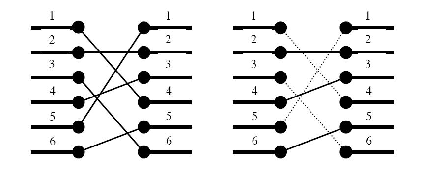
Figure 1. To the left: The two blocks' ports and their signal mapping (4,2,6,3,1,5). To the right: At most three signals may be routed on the silicon surface without crossing each other. The dashed signals must be bridged.
A typical situation is schematically depicted in figure 1. The ports of the two functional blocks are numbered from 1 to p, from top to bottom. The signal mapping is described by a permutation of the numbers 1 to p in the form of a list of p unique numbers
in the range 1 to p, in which the i:th number pecifies which port on the right side should be connected to the i:th port on the left side.
Two signals cross if and only if the straight lines connecting the two ports of each pair do.
[align=left]Input[/align]
On the first line of the input, there is a single positive integer n, telling the number of test scenarios to follow. Each test scenario begins with a line containing a single positive integer p<40000,
the number of ports on the two functional blocks. Then follow p lines, describing the signal mapping: On the i:th line is the port number of the block on the right side which should be connected to the i:th port of the block on the left side.
[align=left]Output[/align]
For each test scenario, output one line containing the maximum number of signals which may be routed on the silicon surface without crossing each other.
[align=left]Sample Input[/align]
4
6
4
2
6
3
1
5
10
2
3
4
5
6
7
8
9
10
1
8
8
7
6
5
4
3
2
1
9
5
8
9
2
3
1
7
4
6
[align=left]Sample Output[/align]
3
9
1
4
说一大推,就是让求最长上升子序列,完全裸题。STL大法好用啊,O(nlogn)算法时间短,代码短。
代码如下:
Bridging signals
Time Limit: 5000/1000 MS (Java/Others) Memory Limit: 65536/32768 K (Java/Others)Total Submission(s): 1291 Accepted Submission(s): 837
[align=left]Problem Description[/align]
'Oh no, they've done it again', cries the chief designer at the Waferland chip factory. Once more the routing designers have screwed up completely, making the signals on the chip connecting the ports of
two functional blocks cross each other all over the place. At this late stage of the process, it is too
expensive to redo the routing. Instead, the engineers have to bridge the signals, using the third dimension, so that no two signals cross. However, bridging is a complicated operation, and thus it is desirable to bridge as few signals as possible. The call
for a computer program that finds the maximum number of signals which may be connected on the silicon surface without rossing each other, is imminent. Bearing in mind that there may be housands of signal ports at the boundary of a functional block, the problem
asks quite a lot of the programmer. Are you up to the task?
Figure 1. To the left: The two blocks' ports and their signal mapping (4,2,6,3,1,5). To the right: At most three signals may be routed on the silicon surface without crossing each other. The dashed signals must be bridged.
A typical situation is schematically depicted in figure 1. The ports of the two functional blocks are numbered from 1 to p, from top to bottom. The signal mapping is described by a permutation of the numbers 1 to p in the form of a list of p unique numbers
in the range 1 to p, in which the i:th number pecifies which port on the right side should be connected to the i:th port on the left side.
Two signals cross if and only if the straight lines connecting the two ports of each pair do.
[align=left]Input[/align]
On the first line of the input, there is a single positive integer n, telling the number of test scenarios to follow. Each test scenario begins with a line containing a single positive integer p<40000,
the number of ports on the two functional blocks. Then follow p lines, describing the signal mapping: On the i:th line is the port number of the block on the right side which should be connected to the i:th port of the block on the left side.
[align=left]Output[/align]
For each test scenario, output one line containing the maximum number of signals which may be routed on the silicon surface without crossing each other.
[align=left]Sample Input[/align]
4
6
4
2
6
3
1
5
10
2
3
4
5
6
7
8
9
10
1
8
8
7
6
5
4
3
2
1
9
5
8
9
2
3
1
7
4
6
[align=left]Sample Output[/align]
3
9
1
4
说一大推,就是让求最长上升子序列,完全裸题。STL大法好用啊,O(nlogn)算法时间短,代码短。
代码如下:
#include<cstdio>
#include<algorithm>
#define INF 0x3f3f3f
using namespace std;
int a[40010],dp[40010];
int main()
{
int n,i,t;
scanf("%d",&t);
while(t--)
{
scanf("%d",&n);
for(i=0;i<n;++i)
{
scanf("%d",&a[i]);
dp[i]=INF;
}
for(i=0;i<n;++i)
*lower_bound(dp,dp+n,a[i])=a[i];
printf("%d\n",lower_bound(dp,dp+n,INF)-dp);
}
return 0;
}

相关文章推荐
- 单例
- Python计算机视觉编程练习6:文本、列表操作
- php引入lucene搜索引擎方法.
- 机器学习 --- 入门
- Solr随笔
- LK光流算法:提高计算精度和增加搜索范围
- 多线程中使用Socket Server的问题
- Struts标签里的type属性
- dhcp的基本配置命令
- [转]IO流详解
- MariaDB数据库介绍之四、Galera Cluster
- Objective-C加强-block代码块和protocol协议
- Oracle ORA-06502 数字或值错误:字符串缓冲区太小
- 一步一步制作yaffs/yaffs2根文件系统(二)---安装BusyBox,构造/bin、/sbin、/usr、linuxr
- <编程之美>2.4 1的数目的解释
- 官方的PSNR和SSIM代码
- 我的iOS学习历程 - UITableView(数据model的使用)
- Google推荐的图片加载库Glide介绍
- bzoj1227 [SDOI2009]虔诚的墓主人(组合公式+离散化+线段树)
- 四则运算app第一阶段冲刺