分布式交换机LACP配置
2015-09-22 14:51
411 查看
NIC Teaming在生产环境使用非常广泛,使用基于IP哈希算法的负载均衡必须满足物理交换机必须支持链路聚合协议(Link Aggregation Control Protocol,以下简称LACP)以及思科私有的端口聚合协议(Port Aggregation Protocol,以下简称PAGP),同时要求端口必须处于同一物理交换机(如果使用思科Nexus交换机VirtualPort Channel功能不需要端口处于同一物理交换机)。大多数使用分布式交换机的环境都使用开放标准的LACP,本节介绍分布式交换机LACP的配置。第1步,使用浏览器登录Web Client,选择分布式交换机”BDnetlab-vDS”,在”管理”标签中的”设置”选择“LACP”,如图4-3-27所示,单击“新建链路聚合组”图标。
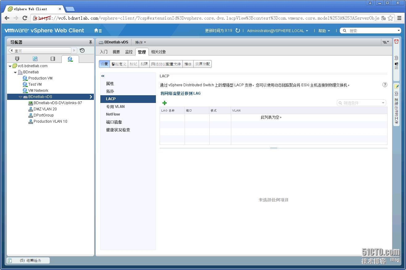
图4-3-27 分布式交换机LACP配置之一
第2步,输入新建链路聚合组的名称以及上行链路端口数,端口数为加入到链路聚合组的数量,LACP的模式配置为”活动”(对应物理交换机LACP的模式为ACTIVE),负载平衡的方式选择”源和目标IP地址、TCP/UDP端口及VLAN”,如图4-3-28所示,单击”确定”按钮。
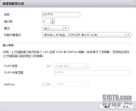
图4-3-28 分布式交换机LACP配置之二 第3步,名为LACP01的链路聚合组创建完成,如图4-3-29所示。
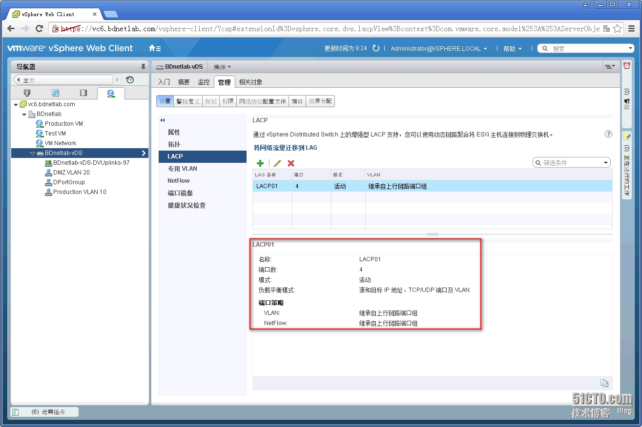
图4-3-29 分布式交换机LACP配置之三
第4步,不少人在完成第3步后就认为LACP配置完成了,实际上只进行了基础的配置,在对应的物理交换机上可以看到网卡line protocol状态为down,以及链路聚合组的状态为down,其原因是新创建的链路聚合组还未添加网卡。BDNETLAB_4503_01#show interfaces g3/13GigabitEthernet3/13 is up, line protocol is down(suspended) Hardware is Gigabit Ethernet Port, address is 000b.fd6c.e3dc (bia000b.fd6c.e3dc) Description: esxi01-trunk MTU1500 bytes, BW 1000000 Kbit, DLY 10 usec, reliability 255/255, txload 1/255, rxload 1/255 BDNETLAB_4503_01#show interfaces port-channel10Port-channel10 is down, line protocol is down(notconnect) Hardware is EtherChannel, address is 0000.0000.0000 (bia 0000.0000.0000) MTU1500 bytes, BW 100000 Kbit, DLY 100 usec, reliability 255/255, txload 1/255, rxload 1/255 第5步,在分布式交换机”BDnetlab-vDS”上单击右键,选择”添加和管理主机“,如图4-3-30所示。

图4-3-30 分布式交换机LACP配置之四
第6步,在添加管理主机窗口选择“管理主机网络”,如图4-3-31所示,单击”下一步”按钮。
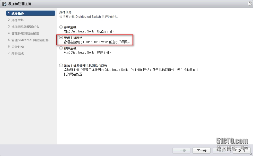
图4-3-31 分布式交换机LACP配置之五
第7步,确定需要使用链路聚合组的ESXi主机,如图4-3-32所示,单击”下一步”按钮。

图4-3-32 分布式交换机LACP配置之六
第8步,选择“管理物理适配器”,将ESXi主机的网卡添加到分布式交换机链路聚合组,如图4-3-33所示,单击”下一步”按钮。

图4-3-33 分布式交换机LACP配置之七
第9步,在4.3.3小节中已经将ESXi主机上的vmnic2和vmnic3网卡添加了分布式交换机上行链路中,现在需要将网卡加入到链路聚合组中,选择网卡后单击”分配上行链路”,如图4-3-34所示。
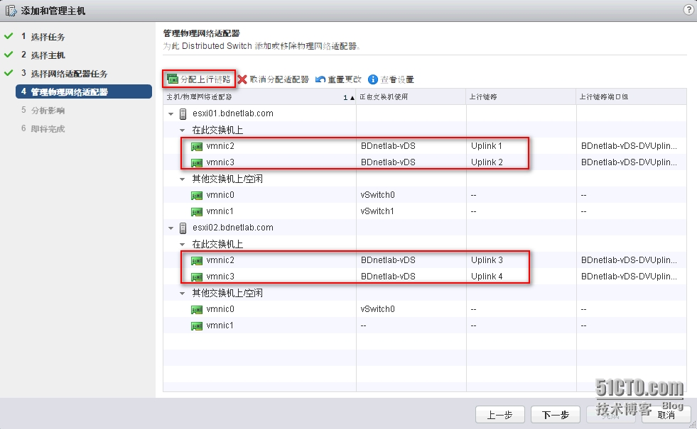
图4-3-34 分布式交换机LACP配置之八
第10步,为网卡选择LACP01端口中的LACP01-0到3任意一个端口,如图4-3-35所示,单击”确定“按钮。

图4-3-35 分布式交换机LACP配置之九
第11步,对原有的网卡进行了重新分配,确认网卡重新分配到上行链路LACP01链路聚合组,如图4-3-36所示。
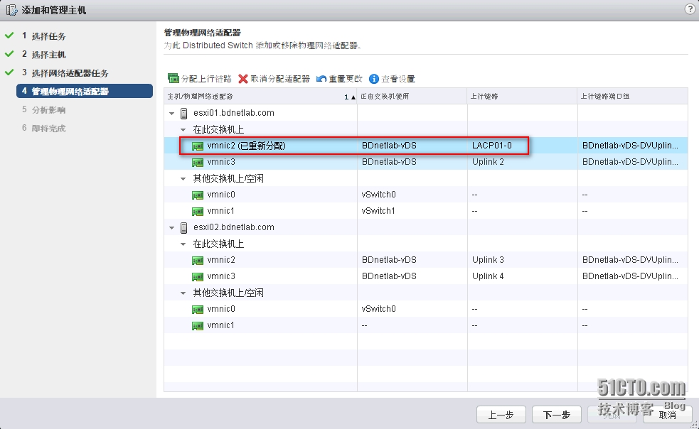
图4-3-36 分布式交换机LACP配置之十
第12步,使用相同的方法将ESXi主机其余的网卡重新分配到上行链路LACP01链路聚合组,如图4-3-37所示,单击”下一步”按钮。
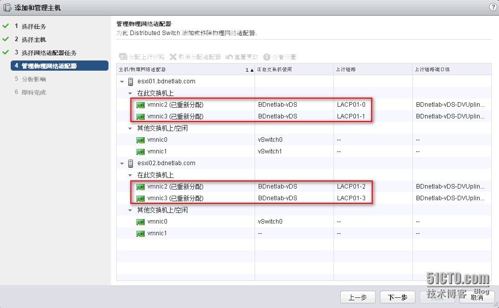
图4-3-37 分布式交换机LACP配置之十一 第13步,系统会自动分析ESXi主机网卡重新分配是否会对现在网络造成影响,如图4-3-38所示,单击”下一步”按钮。
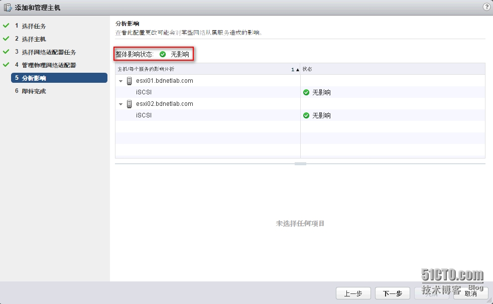
图4-3-38 分布式交换机LACP配置之十二
第14步,确认重新分配网卡参数否正确,如图4-3-39所示,单击”完成”按钮。

图4-3-39 分布式交换机LACP配置之十三 第15步,登录对应的物理交换机上查看网卡以及链路聚合组的状态,这次可以所有状态均为up。BDNETLAB_4503_01#show interfaces g3/13GigabitEthernet3/13 is up, line protocol is up(connected) Hardware is Gigabit Ethernet Port, address is 000b.fd6c.e3dc (bia000b.fd6c.e3dc) Description: esxi01-trunk MTU1500 bytes, BW 1000000 Kbit, DLY 10 usec, reliability 255/255, txload 1/255, rxload 1/255 BDNETLAB_4503_01#show interfaces port-channel10Port-channel10 is up, line protocol is up (connected) Hardware is EtherChannel, address is 000b.fd6c.e3dc (bia 000b.fd6c.e3dc) Description: connetct to esxi01-lacp01 MTU1500 bytes, BW 2000000 Kbit, DLY 10 usec, reliability 255/255, txload 1/255, rxload 1/255 第16步,默认情况下DMZ VLAN 20分布式端口组使用的是4个活动上行链路,LACP01链路聚合组处于未使用状态,如图4-3-40,使用上下箭头可以进行调整。
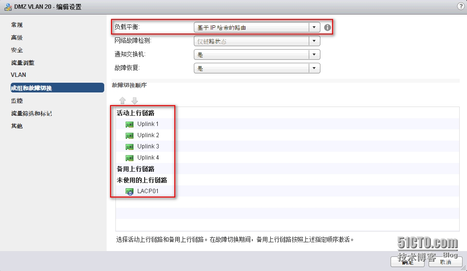
图4-3-40 分布式交换机LACP配置之十四
第17步,将LACP01链路聚合组调整为活动上行链路,Uplink1到4调整到未使用的上行链路,如图4-3-41所示,单击”完成”按钮。
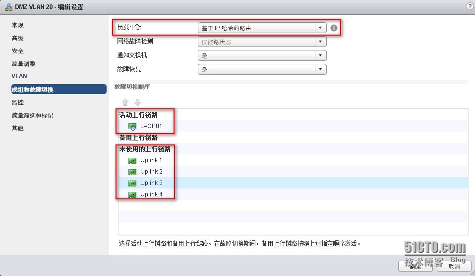
图4-3-41 分布式交换机LACP配置之十五
第18步,分布式端口组不支持链路聚合组与独立上行链路混用,如果备用上行链路中配置独立上行链路,会出现错误提示,如图4-3-42所示。
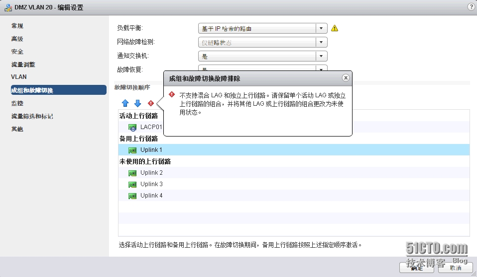
图4-3-42 分布式交换机LACP配置之十六
第19步,分布式端口组DMZ VLAN 20配置LACP01链路聚合组完成,如图4-3-43所示。
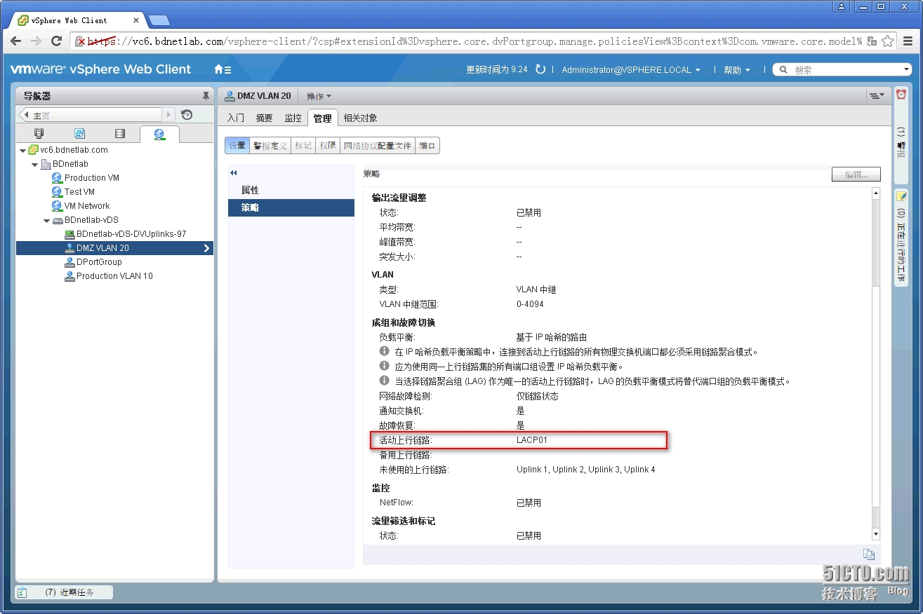
图4-3-43 分布式交换机LACP配置之十七
第20步,对应物理交换机针对LACP完整配置清单:interface Port-channel10 description connetct to esxi01-lacp01 switchport switchport trunk encapsulation dot1q #配置Trunk封装dot1q协议 switchport trunk allowed vlan 10,20,30 switchport mode trunk #配置端口模式为Trunk!interface Port-channel20 description connecto to esxi02-lacp01 switchport switchporttrunk encapsulation dot1q #配置Trunk封装dot1q协议 switchport trunk allowed vlan 10,20,30 switchport mode trunk #配置端口模式为Trunk interface GigabitEthernet3/13 description esxi01-trunk switchport trunk encapsulation dot1q #配置Trunk封装dot1q协议 switchporttrunk allowed vlan 10,20,30 switchport mode trunk #配置端口模式为Trunk channel-group 10 mode active #配置链路聚合协议LACP! interface GigabitEthernet3/14 description esxi01-trunk switchport trunk encapsulation dot1q #配置Trunk封装dot1q协议 switchport trunk allowed vlan 10,20,30 switchport mode trunk #配置端口模式为Trunk channel-group 10 mode active #配置链路聚合协议LACP interface GigabitEthernet3/17 description esxi02-trunk switchport trunk encapsulation dot1q #配置Trunk封装dot1q协议 switchport trunk allowed vlan 10,20,30 switchport mode trunk #配置端口模式为Trunk channel-group 20 mode active #配置链路聚合协议LACP!interface GigabitEthernet3/18 description esxi02-trunk switchport trunk encapsulation dot1q #配置Trunk封装dot1q协议 switchport trunk allowed vlan 10,20,30 switchportmode trunk #配置端口模式为Trunk channel-group 20 mode active #配置链路聚合协议LACP
图4-3-27 分布式交换机LACP配置之一
第2步,输入新建链路聚合组的名称以及上行链路端口数,端口数为加入到链路聚合组的数量,LACP的模式配置为”活动”(对应物理交换机LACP的模式为ACTIVE),负载平衡的方式选择”源和目标IP地址、TCP/UDP端口及VLAN”,如图4-3-28所示,单击”确定”按钮。
图4-3-28 分布式交换机LACP配置之二 第3步,名为LACP01的链路聚合组创建完成,如图4-3-29所示。
图4-3-29 分布式交换机LACP配置之三
第4步,不少人在完成第3步后就认为LACP配置完成了,实际上只进行了基础的配置,在对应的物理交换机上可以看到网卡line protocol状态为down,以及链路聚合组的状态为down,其原因是新创建的链路聚合组还未添加网卡。BDNETLAB_4503_01#show interfaces g3/13GigabitEthernet3/13 is up, line protocol is down(suspended) Hardware is Gigabit Ethernet Port, address is 000b.fd6c.e3dc (bia000b.fd6c.e3dc) Description: esxi01-trunk MTU1500 bytes, BW 1000000 Kbit, DLY 10 usec, reliability 255/255, txload 1/255, rxload 1/255 BDNETLAB_4503_01#show interfaces port-channel10Port-channel10 is down, line protocol is down(notconnect) Hardware is EtherChannel, address is 0000.0000.0000 (bia 0000.0000.0000) MTU1500 bytes, BW 100000 Kbit, DLY 100 usec, reliability 255/255, txload 1/255, rxload 1/255 第5步,在分布式交换机”BDnetlab-vDS”上单击右键,选择”添加和管理主机“,如图4-3-30所示。
图4-3-30 分布式交换机LACP配置之四
第6步,在添加管理主机窗口选择“管理主机网络”,如图4-3-31所示,单击”下一步”按钮。
图4-3-31 分布式交换机LACP配置之五
第7步,确定需要使用链路聚合组的ESXi主机,如图4-3-32所示,单击”下一步”按钮。
图4-3-32 分布式交换机LACP配置之六
第8步,选择“管理物理适配器”,将ESXi主机的网卡添加到分布式交换机链路聚合组,如图4-3-33所示,单击”下一步”按钮。
图4-3-33 分布式交换机LACP配置之七
第9步,在4.3.3小节中已经将ESXi主机上的vmnic2和vmnic3网卡添加了分布式交换机上行链路中,现在需要将网卡加入到链路聚合组中,选择网卡后单击”分配上行链路”,如图4-3-34所示。
图4-3-34 分布式交换机LACP配置之八
第10步,为网卡选择LACP01端口中的LACP01-0到3任意一个端口,如图4-3-35所示,单击”确定“按钮。
图4-3-35 分布式交换机LACP配置之九
第11步,对原有的网卡进行了重新分配,确认网卡重新分配到上行链路LACP01链路聚合组,如图4-3-36所示。
图4-3-36 分布式交换机LACP配置之十
第12步,使用相同的方法将ESXi主机其余的网卡重新分配到上行链路LACP01链路聚合组,如图4-3-37所示,单击”下一步”按钮。
图4-3-37 分布式交换机LACP配置之十一 第13步,系统会自动分析ESXi主机网卡重新分配是否会对现在网络造成影响,如图4-3-38所示,单击”下一步”按钮。
图4-3-38 分布式交换机LACP配置之十二
第14步,确认重新分配网卡参数否正确,如图4-3-39所示,单击”完成”按钮。
图4-3-39 分布式交换机LACP配置之十三 第15步,登录对应的物理交换机上查看网卡以及链路聚合组的状态,这次可以所有状态均为up。BDNETLAB_4503_01#show interfaces g3/13GigabitEthernet3/13 is up, line protocol is up(connected) Hardware is Gigabit Ethernet Port, address is 000b.fd6c.e3dc (bia000b.fd6c.e3dc) Description: esxi01-trunk MTU1500 bytes, BW 1000000 Kbit, DLY 10 usec, reliability 255/255, txload 1/255, rxload 1/255 BDNETLAB_4503_01#show interfaces port-channel10Port-channel10 is up, line protocol is up (connected) Hardware is EtherChannel, address is 000b.fd6c.e3dc (bia 000b.fd6c.e3dc) Description: connetct to esxi01-lacp01 MTU1500 bytes, BW 2000000 Kbit, DLY 10 usec, reliability 255/255, txload 1/255, rxload 1/255 第16步,默认情况下DMZ VLAN 20分布式端口组使用的是4个活动上行链路,LACP01链路聚合组处于未使用状态,如图4-3-40,使用上下箭头可以进行调整。
图4-3-40 分布式交换机LACP配置之十四
第17步,将LACP01链路聚合组调整为活动上行链路,Uplink1到4调整到未使用的上行链路,如图4-3-41所示,单击”完成”按钮。
图4-3-41 分布式交换机LACP配置之十五
第18步,分布式端口组不支持链路聚合组与独立上行链路混用,如果备用上行链路中配置独立上行链路,会出现错误提示,如图4-3-42所示。
图4-3-42 分布式交换机LACP配置之十六
第19步,分布式端口组DMZ VLAN 20配置LACP01链路聚合组完成,如图4-3-43所示。
图4-3-43 分布式交换机LACP配置之十七
第20步,对应物理交换机针对LACP完整配置清单:interface Port-channel10 description connetct to esxi01-lacp01 switchport switchport trunk encapsulation dot1q #配置Trunk封装dot1q协议 switchport trunk allowed vlan 10,20,30 switchport mode trunk #配置端口模式为Trunk!interface Port-channel20 description connecto to esxi02-lacp01 switchport switchporttrunk encapsulation dot1q #配置Trunk封装dot1q协议 switchport trunk allowed vlan 10,20,30 switchport mode trunk #配置端口模式为Trunk interface GigabitEthernet3/13 description esxi01-trunk switchport trunk encapsulation dot1q #配置Trunk封装dot1q协议 switchporttrunk allowed vlan 10,20,30 switchport mode trunk #配置端口模式为Trunk channel-group 10 mode active #配置链路聚合协议LACP! interface GigabitEthernet3/14 description esxi01-trunk switchport trunk encapsulation dot1q #配置Trunk封装dot1q协议 switchport trunk allowed vlan 10,20,30 switchport mode trunk #配置端口模式为Trunk channel-group 10 mode active #配置链路聚合协议LACP interface GigabitEthernet3/17 description esxi02-trunk switchport trunk encapsulation dot1q #配置Trunk封装dot1q协议 switchport trunk allowed vlan 10,20,30 switchport mode trunk #配置端口模式为Trunk channel-group 20 mode active #配置链路聚合协议LACP!interface GigabitEthernet3/18 description esxi02-trunk switchport trunk encapsulation dot1q #配置Trunk封装dot1q协议 switchport trunk allowed vlan 10,20,30 switchportmode trunk #配置端口模式为Trunk channel-group 20 mode active #配置链路聚合协议LACP

相关文章推荐
- Android Manifest 用法
- Android学习笔记(二九):嵌入浏览器
- 峰回路转,Firefox 浏览器即将重返 iOS 平台
- 峰回路转,Firefox 浏览器即将重返 iOS 平台
- Java IO与NIO的一些文件拷贝测试
- Go 语言 Channel 实现原理精要
- dns。dhcp,ftp
- 浏览器 cookie 限制
- 玩转浏览器IE7的5个顶级使用技巧
- 交换机如何配置 新手配置交换机详细教程
- 字符集导致的浏览器跨站脚本攻击分析
- 更改IE浏览器的图标
- C# IP地址与整数之间转换的具体方法
- SQL语句实现查询SQL Server服务器名称和IP地址
- 可以获取客户端的IP地址的sql语句
- 如何创建ajax对象并兼容多个浏览器
- css ie6 ie7 ff的CSS hack使用技巧
- CSS 浏览器的等宽空格问题解决
- 区分IE6,IE7,firefox的CSS hack
- C#如何自动选择出系统中最合适的IP地址