Bridging signals
2015-08-20 20:16
344 查看
[align=left]Problem Description[/align]
[align=left] [/align]
'Oh no, they've done it again', cries the chief designer at the Waferland chip factory. Once more the routing designers have screwed up completely, making the signals on the chip connecting
the ports of two functional blocks cross each other all over the place. At this late stage of the process, it is too
expensive to redo the routing. Instead, the engineers have to bridge the signals, using the third dimension, so that no two signals cross. However, bridging is a complicated operation, and thus it is desirable to bridge as few signals as possible. The call
for a computer program that finds the maximum number of signals which may be connected on the silicon surface without rossing each other, is imminent. Bearing in mind that there may be housands of signal ports at the boundary of a functional block, the problem
asks quite a lot of the programmer. Are you up to the task?
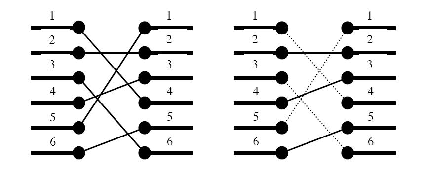
Figure 1. To the left: The two blocks' ports and their signal mapping (4,2,6,3,1,5). To the right: At most three signals may be routed on the silicon surface without crossing each other. The dashed signals must be bridged.
A typical situation is schematically depicted in figure 1. The ports of the two functional blocks are numbered from 1 to p, from top to bottom. The signal mapping is described by a permutation of the numbers 1 to p in the form of a list of p unique numbers
in the range 1 to p, in which the i:th number pecifies which port on the right side should be connected to the i:th port on the left side.
Two signals cross if and only if the straight lines connecting the two ports of each pair do.
[align=left]Input[/align]
[align=left] [/align]
On the first line of the input, there is a single positive integer n, telling the number of test scenarios to follow. Each test scenario begins with a line containing a single positive integer
p<40000, the number of ports on the two functional blocks. Then follow p lines, describing the signal mapping: On the i:th line is the port number of the block on the right side which should be connected to the i:th port of the block on the left side.
[align=left]Output[/align]
[align=left] [/align]
For each test scenario, output one line containing the maximum number of signals which may be routed on the silicon surface without crossing each other.
[align=left]Sample Input[/align]
[align=left] [/align]
[align=left]Sample Output[/align]
[align=left] [/align]
3
9
1
4
[align=left] [/align]
[align=left]二分法[/align]
[align=left] [/align]
'Oh no, they've done it again', cries the chief designer at the Waferland chip factory. Once more the routing designers have screwed up completely, making the signals on the chip connecting
the ports of two functional blocks cross each other all over the place. At this late stage of the process, it is too
expensive to redo the routing. Instead, the engineers have to bridge the signals, using the third dimension, so that no two signals cross. However, bridging is a complicated operation, and thus it is desirable to bridge as few signals as possible. The call
for a computer program that finds the maximum number of signals which may be connected on the silicon surface without rossing each other, is imminent. Bearing in mind that there may be housands of signal ports at the boundary of a functional block, the problem
asks quite a lot of the programmer. Are you up to the task?
Figure 1. To the left: The two blocks' ports and their signal mapping (4,2,6,3,1,5). To the right: At most three signals may be routed on the silicon surface without crossing each other. The dashed signals must be bridged.
A typical situation is schematically depicted in figure 1. The ports of the two functional blocks are numbered from 1 to p, from top to bottom. The signal mapping is described by a permutation of the numbers 1 to p in the form of a list of p unique numbers
in the range 1 to p, in which the i:th number pecifies which port on the right side should be connected to the i:th port on the left side.
Two signals cross if and only if the straight lines connecting the two ports of each pair do.
[align=left]Input[/align]
[align=left] [/align]
On the first line of the input, there is a single positive integer n, telling the number of test scenarios to follow. Each test scenario begins with a line containing a single positive integer
p<40000, the number of ports on the two functional blocks. Then follow p lines, describing the signal mapping: On the i:th line is the port number of the block on the right side which should be connected to the i:th port of the block on the left side.
[align=left]Output[/align]
[align=left] [/align]
For each test scenario, output one line containing the maximum number of signals which may be routed on the silicon surface without crossing each other.
[align=left]Sample Input[/align]
[align=left] [/align]
4
6
4
2
6
3
1
5
10
2
3
4
5
6
7
8
9
10
1
8
8
7
6
5
4
3
2
1
9
5
8
9
2
3
1
7
4
6
[align=left]Sample Output[/align]
[align=left] [/align]
3
9
1
4
[align=left] [/align]
[align=left]二分法[/align]
#include<stdio.h>
#include<algorithm>
#define max 40400
using namespace std;
int a[max],b[max];
int main()
{
int T,n;
scanf("%d",&T);
while(T--)
{
scanf("%d",&n);
int i,len=1,t;//len是用来记录最长上升子序列的长度
for(i=1;i<=n;i++)
scanf("%d",&a[i]);
b[1]=a[1];
for(i=2;i<=n;i++)
{
if(b[len]<a[i])
{
b[++len]=a[i];
continue;
}
else
{
int l=1,r=len,mid;
while(l<=r)
{
mid=(l+r)/2;
if(b[mid]<a[i])
l=mid+1;
else
r=mid-1;

}
b[l]=a[i];//这里不能写成b[mid]=a[i]
}
}
printf("%d\n",len);
}
return 0;
}

相关文章推荐
- hdoj 1242 Rescue
- 用C语言编程求青蛙王子问题
- POJ1477
- HDU 4348 I - To the moon 可持续化
- HDOJ 2041 超级楼梯 (打表法)
- this指针与__thiscall调用方式
- Mysql多实例之mysql服务脚本
- Linux定时任务crontab
- CODEVS 3286 火柴排队
- Oracle Coherence中文教程二十一:使用缓存事件
- HDOJ 2199 Can you solve this equation? (二分法)
- Rotate Array [LeetCode]
- 算法导论——(4)有序统计树(OrderStatisticTree,以红黑树为基本数据结构)
- C语言编程判断一个数是否为素数
- BZOJ1048
- hdu 4300 Clairewd’s message
- Mysql之多实例my.cnf
- Javascript书籍推荐----(步步为赢)
- ASP.Net零碎
- Javascript书籍推荐----(步步为赢)