WPF 3D Primer
2014-11-02 13:57
246 查看
http://www.codeproject.com/Articles/23332/WPF-3D-Primer
Alternatively, you can
update your subscriptions.
Download source and demo project - 25.38 KB
I'm no expert in 3D graphics, this was my first contact with this matter, and I've never used Direct3D or OpenGL, so things had to be extremely simple.
WPF 3D seemed to be the quickest way to build a 3D interface, so I decided to create a small application that just gives the user the ability to rotate and zoom the view on a single solid object.
Although I'm really happy with the result, I'm probably doing some newbie mistakes here, so feel free to point them out.
Visual Studio 2008 Professional (Visual C# 2008 Express should be sufficient)
.NET Framework 3.5 (installed along with Visual Studio)
Basic WPF knowledge
Basic trigonometry knowledge
If you are new to WPF, I strongly suggest you read the excellent articles by
Josh Smith. You can also take a look at the
introductory MSDN article and the part focused on
3D graphics.
It’s based on Direct3D, and therefore it takes advantage of graphic cards (as WPF 2D does)
Full-scene anti-aliasing is disabled by default on Windows XP and enabled by default on Windows Vista (if the graphic card’s driver is
WDDM-Compliant)
The most important thing to note, however, is the different coordinate system that WPF 3D uses, as shown in the figure below:

This difference requires that most interactions with the user (namely mouse events) perform coordinate conversions. As we'll see later on, this operation is actually quite simple.

the main window file to MainWindow.xaml, checking that all references are correct (especially in the
App.xaml file created automatically).
Note: While writing XAML, we will add the

Collapse |
Copy Code
WPF 3D is based on the
We also want the ability to reset the view to its original “status” after the user rotated or zoomed the scene, so we'll also need a button.
For building the window layout, we'll use a grid with 2 rows. The second row will be sized automatically by WPF to occupy as much vertical space as possible, while the first will just wrap its content. We can now add the
Collapse |
Copy Code
The XAML above will result in something like this (notice the black-background grid, the button at the top and the empty

Collapse |
Copy Code
The XAML above adds a
other types of cameras)
inside the
work for the code-behind.
There are
3 types of light sources in WPF: we'll now add two types of them, as shown in the markup below:
Collapse |
Copy Code
The actual contentof the model is specified inside the
The two light sources we used give the scene a good illumination, but feel free to experiment new configurations yourself.
facet.
In WPF 3D (and possibly Direct3D and/or OpenGL, as I said I'm not an expert) a facet has a
direction, that defines the side the facet will be visible from, as you can see in the figure below:

Although you can explicitly specify the normals of each vertex (not triangle) composing a facet (using the
in the figure above: vertices are labelled 0, 1 and
2, and the direction of the faced is represented by the arrow labelled “+”. We add them in the order
0, 1, 2.
We'll create the solid shown in the figure below (a truncated pyramid) by adding its 8 vertices and then defining the 12 triangles needed to define all its faces.

We define the
Window1.xaml.cs if you didn't rename it). This method is then invoked in the constructor of the class, and it just adds the vertices one-by-one, in the order specified in the figure (this is not actually a requirement, but it makes things more clear).
Collapse |
Copy Code
Although we used the term “face”, it’s worth noting that we still don't have any real face defined. In order to do that, we have to build the triangles that compose each face of the solid from the points we just created: we add each triangle declaring its
vertices in the proper order, so that the direction of each facet points outwards the solid.
Collapse |
Copy Code
As you can see, we defined 12 triangles using only 8 vertices. The only thing we have to do now is to actually add the mesh to the scene, wrapping it in an instance of
For the purposes of the application, we'll need a reference to the geometry for later use, so we add a new
Collapse |
Copy Code
Then, we can complete the
Collapse |
Copy Code
As you can see, we used a simple
MSDN). We also set the
Now, if we hit the F5 button, we should see something like this:

The main window now displays our test solid, front facing. Try to resize the window and see how WPF seamlessly scales the
IntelliSense is our friend:
Let the IntelliSense popup appear, and hit enter. Visual Studio should have created a handler named
The handler has to do one thing only: move our camera on the Zaxis. Binding this movement with the wheel scroll value is quite tricky and after some trial-and-error, I found that the following code works well:
Collapse |
Copy Code
We don't touch the
We also want to let the Reset button we defined in XAML reset the camera position, so we add a handler for its
Collapse |
Copy Code
Just in case you're curious, the XAML code for the
Collapse
| Copy Code
You can now hit F5 again, verifying that zooming works and that the Reset button does its work properly.
The difficult part of this task is to map a 2D vector (the mouse movement) to a 3D rotation of the solid. It took me a while to figure it out, but the mouse movement vector can be easily converted to a rotation angle, applied to the solid around a rotation
axis that is coplanar with the screen and perpendicular to the mouse movement vector, as shown in the figure below.

The rotation axis is pinned in the origin (0,0,0) because the solid is centered in the origin itself, and both the mouse movement vector and the rotation axis have the
The rotation axis has a direction, indicated by the arrow in the previous figure. Angles are always calculated in clockwise direction, so if you rotate the solid with a positive angle, it will rotate leftwards:

In order to properly calculate the rotation axis, we first need to calculate the angle of the mouse movement vector. Basic trigonometry tells us that the angle,
alpha, is computed as follows:

We also need to take care of the sign of
In order to implement the rotation function, we need three more handlers for the
Collapse
| Copy Code
We also need a couple of variables in the
Collapse
| Copy Code
The
Collapse
| Copy Code
The
Collapse
| Copy Code
The method first checks if the mouse left button is pressed; if not, it exists. The mouse
The angle of the mouse movement vector is then calculated with the formula we saw before, with three different cases:
If
If
If
The angle of the rotation axis (

The rotation
The rotation
Collapse
| Copy Code
The only thing we have to do now is to apply a transformation to the geometry. Since we want to rotate the solid (but it’s possible to do
many other things), we have to add an instance of
The constructor of
MSDN). Since we want to apply a rotation around an axis and by a given angle, we use
So far I omitted a detail. The rotation axis is not sufficient to define the actual axis of the rotation, because it also needs a center which is, in our case, the origin. The constructor of
Finally, we can add our transform to the transform collection:
Collapse
| Copy Code
Again, there is a fundamental detail to note. Every transform we apply to the solid is absolute. This means that if we apply two transforms in sequence, the latter overrides the first. For this reason, we use a
The last thing to do is to store the current mouse position in the
We can now update the behavior of the Reset button so that, besides resetting the position of the camera, it also removes all the transforms applied to the solid (mitigating the memory leak we mentioned above).
Collapse
| Copy Code
Now you're ready to hit F5 again and see the final result. If you are running Windows Vista, you can also admire the full-scene anti-aliasing filter applied to the edges of the solid.
Alternatively, you can
update your subscriptions.
Download source and demo project - 25.38 KB
Introduction
In the last couple of days, I had to evaluate the possibility to build a GUI displaying a solid shape to the user, allowing her or him to perform some basic operations, above all rotating and zooming the view.I'm no expert in 3D graphics, this was my first contact with this matter, and I've never used Direct3D or OpenGL, so things had to be extremely simple.
WPF 3D seemed to be the quickest way to build a 3D interface, so I decided to create a small application that just gives the user the ability to rotate and zoom the view on a single solid object.
Although I'm really happy with the result, I'm probably doing some newbie mistakes here, so feel free to point them out.
Requirements
In order to build this application, we need:Visual Studio 2008 Professional (Visual C# 2008 Express should be sufficient)
.NET Framework 3.5 (installed along with Visual Studio)
Basic WPF knowledge
Basic trigonometry knowledge
If you are new to WPF, I strongly suggest you read the excellent articles by
Josh Smith. You can also take a look at the
introductory MSDN article and the part focused on
3D graphics.
Step 0 - The Basics
There is not much to know on WPF 3D, except for a couple of facts:It’s based on Direct3D, and therefore it takes advantage of graphic cards (as WPF 2D does)
Full-scene anti-aliasing is disabled by default on Windows XP and enabled by default on Windows Vista (if the graphic card’s driver is
WDDM-Compliant)
The most important thing to note, however, is the different coordinate system that WPF 3D uses, as shown in the figure below:
This difference requires that most interactions with the user (namely mouse events) perform coordinate conversions. As we'll see later on, this operation is actually quite simple.
Step 1 - Creating the Visual Studio Project
This step is easy, you just need to create a new WPF Application project in Visual Studio, targeting the .NET Framework 3.5. Take a look at the figure below:Step 2 - Preparing the Main Window
Modify the Window1.xaml file that the Project Wizard created for you, setting the window title and dimensions to something that fits your preferences. Since this is a test application, we won't care much about object names and such, but I renamedthe main window file to MainWindow.xaml, checking that all references are correct (especially in the
App.xaml file created automatically).
Note: While writing XAML, we will add the
x:Nameattribute only to elements we want to access programmatically from the code-behind, leaving all the others unnamed.
Collapse |
Copy Code
<Window x:Class="Wpf3DTest.MainWindow"
xmlns="http://schemas.microsoft.com/winfx/2006/xaml/presentation"
xmlns:x="http://schemas.microsoft.com/winfx/2006/xaml"
Title="WPF 3D Test"
Height="400" Width="400">
<Grid>
</Grid>
</Window>
WPF 3D is based on the
Viewport3DUI element, which is in charge of rendering the 3D scene on the screen, so we'll surely need an instance of that object.
We also want the ability to reset the view to its original “status” after the user rotated or zoomed the scene, so we'll also need a button.
For building the window layout, we'll use a grid with 2 rows. The second row will be sized automatically by WPF to occupy as much vertical space as possible, while the first will just wrap its content. We can now add the
Viewport3Dand the
Buttonwe need.
Collapse |
Copy Code
<Grid Background="Black">
<Grid.RowDefinitions>
<RowDefinition Height="Auto" />
<RowDefinition Height="*" />
</Grid.RowDefinitions>

<Button x:Name="button" Grid.Row="0" Content="Reset" />

<Viewport3D x:Name="viewport" Grid.Row="1">
</Viewport3D>
</Grid>
The XAML above will result in something like this (notice the black-background grid, the button at the top and the empty
viewportfilling the window):
Step 3 - The Camera
Every 3D scene in WPF should have a camera, otherwise it won't be rendered on the screen. Given that we won't need to add or remove it at runtime, we can just use a bit of XAML.Collapse |
Copy Code
<Viewport3D.Camera>
<PerspectiveCamera x:Name="camera" FarPlaneDistance="50"
NearPlaneDistance="0" LookDirection="0,0,-10" UpDirection="0,1,0"
Position="0,0,5" FieldOfView="45" />
</Viewport3D.Camera>
The XAML above adds a
PerspectiveCamera(although there are
other types of cameras)
inside the
Viewport3Delement.
FarPlaneDistanceand
NearPlaneDistancerepresent the range within which the camera will display elements. When an element is too far from or too close to the camera, it won't be displayed.
FieldOfViewcan be safely set to
45in most cases, giving us a natural perspective view.
LookDirectionis the point the camera “looks at”: we set it to a point with a negative Zcoordinate.
UpDirectionis the vertical axis of the camera: we set it to be coincident with the Y axis.
Step 4 - Preparing the 3D Model
Thecontentof the
viewportis described using an instance of the
ModelVisual3DUI element (MSDN) inheriting from the abstract class
Model3D. Inside this object, we can basically add geometries (including their materials) and lights. Given that our application might want to load 3D models from an external source, we now only add the lights using XAML, leaving the rest of the
work for the code-behind.
There are
3 types of light sources in WPF: we'll now add two types of them, as shown in the markup below:
Collapse |
Copy Code
<ModelVisual3D x:Name="model">
<ModelVisual3D.Content>
<Model3DGroup x:Name="group">
<AmbientLight Color="DarkGray" />
<DirectionalLight Color="White" Direction="-5,-5,-7" />
</Model3DGroup>
</ModelVisual3D.Content>
</ModelVisual3D>
The actual contentof the model is specified inside the
ModelVisual3D.Contentelement. Since we have more than one item, we wrap all of them with a
Model3DGroupelement (MSDN).The XAML above adds a dark grey (i.e. a very dim light)
AmbientLightand a white
DirectionalLight, pointing in the point (-5, -5, -7) (directional lights don't have a position, they just “look” towards the specified direction).
The two light sources we used give the scene a good illumination, but feel free to experiment new configurations yourself.
Mesh Basics
A mesh is a 3D object built using only triangles. Each triangle has obviously three 3D vertices, combined together to form a small surface called afacet.
In WPF 3D (and possibly Direct3D and/or OpenGL, as I said I'm not an expert) a facet has a
direction, that defines the side the facet will be visible from, as you can see in the figure below:
Although you can explicitly specify the normals of each vertex (not triangle) composing a facet (using the
Normalsproperty of the
MeshGeometry3Dclass), WPF can automatically calculate them using the sequence used to add the vertices. If we add the vertices in counterclockwise order, the faced direction will “point towards us”, as shown
in the figure above: vertices are labelled 0, 1 and
2, and the direction of the faced is represented by the arrow labelled “+”. We add them in the order
0, 1, 2.
Adding the 3D Geometry
In our test application, we're going to add the 3D object programmatically from the code-behind C# file.We'll create the solid shown in the figure below (a truncated pyramid) by adding its 8 vertices and then defining the 12 triangles needed to define all its faces.
We define the
BuildSolidmethod in the code-behind file MainWindow.xaml.cs (or
Window1.xaml.cs if you didn't rename it). This method is then invoked in the constructor of the class, and it just adds the vertices one-by-one, in the order specified in the figure (this is not actually a requirement, but it makes things more clear).
Collapse |
Copy Code
// Define 3D mesh object
MeshGeometry3D mesh = new MeshGeometry3D();
// Front face
mesh.Positions.Add(new Point3D(-0.5, -0.5, 1));
mesh.Positions.Add(new Point3D(0.5, -0.5, 1));
mesh.Positions.Add(new Point3D(0.5, 0.5, 1));
mesh.Positions.Add(new Point3D(-0.5, 0.5, 1));
// Back face
mesh.Positions.Add(new Point3D(-1, -1, -1));
mesh.Positions.Add(new Point3D(1, -1, -1));
mesh.Positions.Add(new Point3D(1, 1, -1));
mesh.Positions.Add(new Point3D(-1, 1, -1));
Although we used the term “face”, it’s worth noting that we still don't have any real face defined. In order to do that, we have to build the triangles that compose each face of the solid from the points we just created: we add each triangle declaring its
vertices in the proper order, so that the direction of each facet points outwards the solid.
Collapse |
Copy Code
// Front face
mesh.TriangleIndices.Add(0);
mesh.TriangleIndices.Add(1);
mesh.TriangleIndices.Add(2);
mesh.TriangleIndices.Add(2);
mesh.TriangleIndices.Add(3);
mesh.TriangleIndices.Add(0);
// Back face
mesh.TriangleIndices.Add(6);
mesh.TriangleIndices.Add(5);
mesh.TriangleIndices.Add(4);
mesh.TriangleIndices.Add(4);
mesh.TriangleIndices.Add(7);
mesh.TriangleIndices.Add(6);
// Right face
mesh.TriangleIndices.Add(1);
mesh.TriangleIndices.Add(5);
mesh.TriangleIndices.Add(2);
mesh.TriangleIndices.Add(5);
mesh.TriangleIndices.Add(6);
mesh.TriangleIndices.Add(2);
// Other faces (see complete source code)...
As you can see, we defined 12 triangles using only 8 vertices. The only thing we have to do now is to actually add the mesh to the scene, wrapping it in an instance of
GeometryModel3D.
For the purposes of the application, we'll need a reference to the geometry for later use, so we add a new
privatemember to the class.
Collapse |
Copy Code
// Reference to the geometry for later use
private GeometryModel3D mGeometry;
Then, we can complete the
BuildSolidmethod with the following code, which creates the geometry object and adds it to the
Model3DGroup(named
group) seen a while ago in the XAML of the main window.
Collapse |
Copy Code
// Geometry creation
mGeometry = new GeometryModel3D(mesh, new DiffuseMaterial(Brushes.YellowGreen));
mGeometry.Transform = new Transform3DGroup();
group.Children.Add(mGeometry);
As you can see, we used a simple
DiffuseMaterialto color the solid, but you can take a look at the different options that WPF 3D offers in this field (see
MSDN). We also set the
Transformproperty to a new instance of the
Transform3DGroupclass, which is a container for transform objects, as we'll see later.
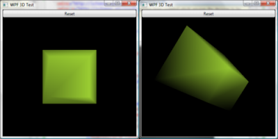
Now, if we hit the F5 button, we should see something like this:
The main window now displays our test solid, front facing. Try to resize the window and see how WPF seamlessly scales the
viewportand the solid.
Step 5 - Implementing the Zoom Functionality
For the sake of simplicity, we're going to implement the zoom functionality so that it will be accessible only using the mouse wheel. We just need to implement a handler for theMouseWheelevent of the main
gridelement in the window. In this case,
IntelliSense is our friend:
Let the IntelliSense popup appear, and hit enter. Visual Studio should have created a handler named
Grid_MouseWheel.
The handler has to do one thing only: move our camera on the Zaxis. Binding this movement with the wheel scroll value is quite tricky and after some trial-and-error, I found that the following code works well:
Collapse |
Copy Code
private void Grid_MouseWheel(object sender, MouseWheelEventArgs e) {
camera.Position = new Point3D(
camera.Position.X,
camera.Position.Y,
camera.Position.Z- e.Delta / 250D);
}
We don't touch the
Xand
Yposition of the camera, we just modify its position on the
Zaxis.
We also want to let the Reset button we defined in XAML reset the camera position, so we add a handler for its
Clickevent (in the same way we added the handler for the
grid’s
MouseWheelevent), and add the following code to it, which resets the Zvalue of the camera position to
5:
Collapse |
Copy Code
private void Button_Click(object sender, RoutedEventArgs e) {
camera.Position = new Point3D(
camera.Position.X,
camera.Position.Y, 5);
}
Just in case you're curious, the XAML code for the
buttonelement is updated as follows.
Collapse
| Copy Code
<Button x:Name="button" Grid.Row="0" Content=" Reset"Click="Button_Click" />
You can now hit F5 again, verifying that zooming works and that the Reset button does its work properly.
Step 6 - Implementing the 3D Rotation Functionality
We want now to enable the user to rotate the solid with her mouse, very much like CAD applications. This is the toughest part of the demo, but with a bit of trigonometry we should get away quite quickly.The difficult part of this task is to map a 2D vector (the mouse movement) to a 3D rotation of the solid. It took me a while to figure it out, but the mouse movement vector can be easily converted to a rotation angle, applied to the solid around a rotation
axis that is coplanar with the screen and perpendicular to the mouse movement vector, as shown in the figure below.
The rotation axis is pinned in the origin (0,0,0) because the solid is centered in the origin itself, and both the mouse movement vector and the rotation axis have the
Zcoordinate set to zero, so they are coplanar with the
XYplane.
The rotation axis has a direction, indicated by the arrow in the previous figure. Angles are always calculated in clockwise direction, so if you rotate the solid with a positive angle, it will rotate leftwards:
In order to properly calculate the rotation axis, we first need to calculate the angle of the mouse movement vector. Basic trigonometry tells us that the angle,
alpha, is computed as follows:
We also need to take care of the sign of
dxand
dy(mouse position delta in
Xand
Y), as we'll see directly in the code.
In order to implement the rotation function, we need three more handlers for the
MouseDown,
MouseUpand
MouseMoveevents of the main
grid:
Collapse
| Copy Code
<Grid Background="Black" MouseWheel="Grid_MouseWheel"
MouseDown="Grid_MouseDown" MouseUp="Grid_MouseUp"
MouseMove="Grid_MouseMove">
We also need a couple of variables in the
MainWindowclass (besides the previously defined
mGeometry):
Collapse
| Copy Code
private GeometryModel3D mGeometry;
private bool mDown;
private Point mLastPos;
mDownis
truewhen the mouse left button is pressed,
falseotherwise.
mLastPoscontains the last position of the mouse pointer relative to the
viewport(this is very important, as we're going to see).
The
MouseDownand
MouseUpevent handlers are quite simple, they just toggle
mDown.
Collapse
| Copy Code
private void Grid_MouseUp(object sender, MouseButtonEventArgs e) {
mDown = false;
}

private void Grid_MouseDown(object sender, MouseButtonEventArgs e) {
if(e.LeftButton != MouseButtonState.Pressed) return;
mDown = true;
Point pos = Mouse.GetPosition(viewport);
mLastPos = new Point(
pos.X- viewport.ActualWidth / 2,
viewport.ActualHeight / 2 - pos.Y);
} MouseDownactually does a little more: it stores the first position of the mouse just after its left button is pressed. The position is relative to the
viewport(
Mouse.GetPositiondoes that), and it is then converted from the 2D coordinate system to the 3D coordinate system, as mentioned at the beginning of the article: the
Xand
Zcoordinates must be adjusted using the
ActualWidthand
ActualHeightproperties of the
viewportelement.
The
MouseMovehandler has a lot of work to do. See the complete code:
Collapse
| Copy Code
private void Grid_MouseMove(object sender, MouseEventArgs e) {
if(!mDown) return;
Point pos = Mouse.GetPosition(viewport);
Point actualPos = new Point(
pos.X- viewport.ActualWidth / 2,
viewport.ActualHeight / 2 - pos.Y);
double dx = actualPos.X- mLastPos.X;
double dy = actualPos.Y - mLastPos.Y;
double mouseAngle = 0;

if(dx != 0 && dy != 0) {
mouseAngle = Math.Asin(Math.Abs(dy) /
Math.Sqrt(Math.Pow(dx, 2) + Math.Pow(dy, 2)));
if(dx < 0 && dy > 0) mouseAngle += Math.PI / 2;
else if(dx < 0 && dy < 0) mouseAngle += Math.PI;
else if(dx > 0 && dy < 0) mouseAngle += Math.PI * 1.5;
}
else if(dx == 0 && dy != 0) {
mouseAngle = Math.Sign(dy) > 0 ? Math.PI / 2 : Math.PI * 1.5;
}
else if(dx != 0 && dy == 0) {
mouseAngle = Math.Sign(dx) > 0 ? 0 : Math.PI;
}

double axisAngle = mouseAngle + Math.PI / 2;

Vector3D axis = new Vector3D(
Math.Cos(axisAngle) * 4,
Math.Sin(axisAngle) * 4, 0);

double rotation = 0.02 *
Math.Sqrt(Math.Pow(dx, 2) + Math.Pow(dy, 2));

Transform3DGroup group = mGeometry.Transform as Transform3DGroup;
QuaternionRotation3D r =
new QuaternionRotation3D(
new Quaternion(axis, rotation * 180 / Math.PI));group.Children.Add(new RotateTransform3D(r));

mLastPos = actualPos;
}
The method first checks if the mouse left button is pressed; if not, it exists. The mouse
dxand
dyvalues are then calculated using the previous position stored in
mLastPos, converting the current position to the 3D coordinate system as shown for the
Grid_MouseDownevent handler.
The angle of the mouse movement vector is then calculated with the formula we saw before, with three different cases:
If
dxand
dyare both different from zero,
mouseAngleis computed using the absolute value of
dy, and then it’s corrected according to the sign of both
dxand
dy.
If
dxis zero,
mouseAnglemust be either 90 or 270 degrees (we use the sign of
dy).
If
dyis zero,
mouseAnglemust be either 0 or 180 degrees (we use the sign of
dx).
The angle of the rotation axis (
axisAngle) is calculated adding 90 degrees to the mouse movement vector angle. Keep in mind that these angles are always referred to the
Xaxis.
The rotation
axis(instance of
Vector3D) is then calculated from the
axisAngle, leaving the
Zcoordinate to zero.
The rotation
angleis calculated as the module of the mouse movement angle multiplied for a factor of
0.01, producing a smooth rotation:
Collapse
| Copy Code
double rotation = 0.01 * Math.Sqrt(Math.Pow(dx, 2) + Math.Pow(dy, 2));
The only thing we have to do now is to apply a transformation to the geometry. Since we want to rotate the solid (but it’s possible to do
many other things), we have to add an instance of
RotateTransform3Dto the
Transform3DGroupcollection we stored in the
Transformproperty of the geometry (have a look at the
BuildSolidmethod). We cast the collection and store it in the
groupvariable.
The constructor of
RotateTransform3Dneeds an instance of a class inheriting from
Rotation3Ddescribing the rotation to apply (see
MSDN). Since we want to apply a rotation around an axis and by a given angle, we use
QuaternionRotation3Dand we instantiate it with
axisand the
rotationangle (in degrees, not in radians).
So far I omitted a detail. The rotation axis is not sufficient to define the actual axis of the rotation, because it also needs a center which is, in our case, the origin. The constructor of
RotateTransform3Daccepts an optional parameter that allows to specify the center of the rotation. If omitted, the origin is used.
Finally, we can add our transform to the transform collection:
Collapse
| Copy Code
group.Children.Add(new RotateTransform3D(r));
Again, there is a fundamental detail to note. Every transform we apply to the solid is absolute. This means that if we apply two transforms in sequence, the latter overrides the first. For this reason, we use a
Transform3DGroup(inheriting from
Transform3D) to store subsequent transforms, one for every mouse movement (as you can imagine, this constitutes a memory leak, but for our testing purposes, it is not a problem).
The last thing to do is to store the current mouse position in the
mLastPosvariable, so that the next mouse move will compute correct delta
X/
Yvalues.
We can now update the behavior of the Reset button so that, besides resetting the position of the camera, it also removes all the transforms applied to the solid (mitigating the memory leak we mentioned above).
Collapse
| Copy Code
private void Button_Click(object sender, RoutedEventArgs e) {
camera.Position = new Point3D(
camera.Position.X,
camera.Position.Y, 5);
mGeometry.Transform = new Transform3DGroup();
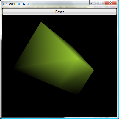
}Now you're ready to hit F5 again and see the final result. If you are running Windows Vista, you can also admire the full-scene anti-aliasing filter applied to the edges of the solid.
Conclusion
Although there is still much work to do before obtaining a full-featured 3D user interface, we explored some interesting features of WPF 3D and we are a little more aware of its advantages and problems.
相关文章推荐
- 用WPF创建3D Content
- WPF3D学习,立方体的绘制
- 最优化WPF 3D性能(基于“Tier-2”硬件)
- WPF 3D 获取鼠标在场景的3d坐标
- 3D Math Primer for Game Programmers (quaternion)
- [Map 3D开发实战系列] Map Resource Explorer 之四-- Map3D开发中的WPF
- 采用WPF框架编写的3D软渲染Demo
- 3D Math Primer for Game Programmers
- WPF中的3D特性和常见的几个类
- WPF中反转3D列表项
- 用WPF创建3D Content
- WPF 3D:使用变换中的TranslateTransform3D
- Improving 3D performance in WPF
- WPF 图片浏览 伪3D效果
- WPF 图片浏览 伪3D效果
- WPF 3D动态加载模型文件
- 3D Math Primer for Game Programmers (View Matrix)
- Rendering Transparent 3D Surfaces in WPF with C#(转载)
- WPF 3D 常用类(1)
- 用WPF创建3D Content