opencv中Bayer 图像到RGB图像装换的问题
2014-07-02 22:17
260 查看
在将bayer图像转换成为rgb的时候遇到的问题
一直解决不了的问题出现在imread的使用上。
bayer图像是 one channel的图像,
如果简单的用imread,用defualt的参数的话,读出来的是3 channels的matrix。
而 cvtColor(source, destination, CV_BayerRG2BGR) 是将one channel 转换成 3 channel 图像的。
解决办法就是把imread 的参数设为0 或者 -1
此处的bayer pattern filter 需要从camera处获取
具体bayer pattern 介绍如下
copy 自:http://www.tldp.org/HOWTO/libdc1394-HOWTO/concepts.html
is actually a Bayer Pattern. We will give an overview of Bayer Patterns and how they are used to get a colored image in this section.
Digital cameras use a solid-state device called an image sensor. These fingernail-sized silicon chips contain millions of photosensitive diodes called photosites. When you take a picture
with a digital camera, the intensity of light hitting each photo site on the sensor is recorded as a signal. Depending on the camera, either 12 or 14 bits of data are recorded. At 12 bits, the camera can record 4,096 levels of brightness. At 14 bits, the camera
can record 16,384 levels of brightness. This is referred to as bit depth. The higher the bit depth, the finer is the detail, the smoother the transition between tones, and the higher the dynamic range (the ability of the camera to hold detail in both
highlighted and shadowed areas). But at capture, digital images are grayscale, not color. To record color information, each pixel on the sensor is covered with a red, green, or blue filter, with the colors alternating. A common arrangement of color filters
is the Bayer Pattern array that alternates colors, but that also uses twice as many green filters as red and blue. Twice as many green filters are used because our eyes are more sensitive to green. This
pattern, or sequence, of filters can vary, but the widely adopted Bayer Pattern, which was invented at Kodak, is a repeating 2x2 arrangement. Each pixel has been made sensitive only to one color (one spectral band).
A Typical Bayer Pattern will look like this:
Figure 5. Bayer Pattern
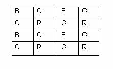
The tile or square (pixel) labeled B means this particular tile is sensitive only to Blue light, and so on.
The Bayer Patterns may be classified into 4 types, depending on how we have arranged the colors. The naming of the Bayer Pattern is done by taking a 2x2 matrix from the top most corner of the pattern
and the colors being read in (0,0),(0,1),(1,0),(1,1) order. So for the above Bayer Pattern, if we take the 2x2 matrix as:
Figure 6. BGGR Pattern
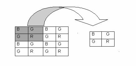
The pattern is therefore known as BGGR
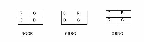
The other possible patterns are:
Figure 7. Other Patterns
The image we obtained in the previous example was a Bayer Pattern image also known as a RAW image. This was stored in camera.capture_buffer. In order to view what we
have captured we convert this RAW image to .PGM by adding a header (look at the explanation in Section 4.4).
In order to get a colored image, the Bayer Pattern image is converted to a RGB image. A RGB image is an enhanced version of the Bayer Pattern image; we try to find the value of the two missing
colors at each pixel (remember that each pixel of the sensor is covered by Bayer Pattern filter so we get a single color at any pixel by default). This is done by using different algorithms like Nearest Neighbor, Edge Sense, and so on:
Figure 8. RAW to RGB
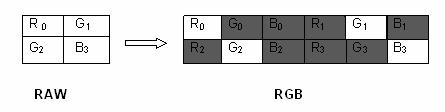
where the shaded values are to be calculated by the algorithm. Subscript denotes the tile on the Bayer Pattern to which the value of R, G, and B belongs. Note that the image size will become 3 times
the Bayer Pattern. In order to view the RGB image we convert it to a Bit Map, or .BMP image, by adding a bitmap header.
To get a clear picture of what's happening, we have provided the following diagram:
Mat bayer = imread("/home/pan/Desktop/data/Testaufbau_Ecoflac153.tif",-1);
Mat bayer2rgb;
bayer2rgb.create(bayer.rows,bayer.cols,CV_8UC3);
cvtColor(bayer,bayer2rgb,CV_BayerRG2BGR);
vector<Mat> difChan;
split(bayer2rgb,difChan);
//    imshow("Bayer Pattern",difChan[0]);
imwrite("img_b.jpg",difChan[0]);
imwrite("img_r.jpg",difChan[1]);
imwrite("img_g.jpg",difChan[2]);
一直解决不了的问题出现在imread的使用上。
bayer图像是 one channel的图像,
如果简单的用imread,用defualt的参数的话,读出来的是3 channels的matrix。
而 cvtColor(source, destination, CV_BayerRG2BGR) 是将one channel 转换成 3 channel 图像的。
解决办法就是把imread 的参数设为0 或者 -1
此处的bayer pattern filter 需要从camera处获取
具体bayer pattern 介绍如下
copy 自:http://www.tldp.org/HOWTO/libdc1394-HOWTO/concepts.html
4.6. How to get color images: Bayer Pattern Concepts
The image grabbed by the sample code in the previous section is not colored (we have intentionally used the words "not colored," since the image is not gray-scale either). Itis actually a Bayer Pattern. We will give an overview of Bayer Patterns and how they are used to get a colored image in this section.
Digital cameras use a solid-state device called an image sensor. These fingernail-sized silicon chips contain millions of photosensitive diodes called photosites. When you take a picture
with a digital camera, the intensity of light hitting each photo site on the sensor is recorded as a signal. Depending on the camera, either 12 or 14 bits of data are recorded. At 12 bits, the camera can record 4,096 levels of brightness. At 14 bits, the camera
can record 16,384 levels of brightness. This is referred to as bit depth. The higher the bit depth, the finer is the detail, the smoother the transition between tones, and the higher the dynamic range (the ability of the camera to hold detail in both
highlighted and shadowed areas). But at capture, digital images are grayscale, not color. To record color information, each pixel on the sensor is covered with a red, green, or blue filter, with the colors alternating. A common arrangement of color filters
is the Bayer Pattern array that alternates colors, but that also uses twice as many green filters as red and blue. Twice as many green filters are used because our eyes are more sensitive to green. This
pattern, or sequence, of filters can vary, but the widely adopted Bayer Pattern, which was invented at Kodak, is a repeating 2x2 arrangement. Each pixel has been made sensitive only to one color (one spectral band).
A Typical Bayer Pattern will look like this:
Figure 5. Bayer Pattern
The tile or square (pixel) labeled B means this particular tile is sensitive only to Blue light, and so on.
The Bayer Patterns may be classified into 4 types, depending on how we have arranged the colors. The naming of the Bayer Pattern is done by taking a 2x2 matrix from the top most corner of the pattern
and the colors being read in (0,0),(0,1),(1,0),(1,1) order. So for the above Bayer Pattern, if we take the 2x2 matrix as:
Figure 6. BGGR Pattern
The pattern is therefore known as BGGR
The other possible patterns are:
Figure 7. Other Patterns
The image we obtained in the previous example was a Bayer Pattern image also known as a RAW image. This was stored in camera.capture_buffer. In order to view what we
have captured we convert this RAW image to .PGM by adding a header (look at the explanation in Section 4.4).
In order to get a colored image, the Bayer Pattern image is converted to a RGB image. A RGB image is an enhanced version of the Bayer Pattern image; we try to find the value of the two missing
colors at each pixel (remember that each pixel of the sensor is covered by Bayer Pattern filter so we get a single color at any pixel by default). This is done by using different algorithms like Nearest Neighbor, Edge Sense, and so on:
Figure 8. RAW to RGB
where the shaded values are to be calculated by the algorithm. Subscript denotes the tile on the Bayer Pattern to which the value of R, G, and B belongs. Note that the image size will become 3 times
the Bayer Pattern. In order to view the RGB image we convert it to a Bit Map, or .BMP image, by adding a bitmap header.
To get a clear picture of what's happening, we have provided the following diagram:

相关文章推荐
- OpenCV ios 摄像头获取和磁盘读取的图像RGB顺序问题
- opencv图像显示遇到的一个问题
- opencv 解决读图像宽度大于1400 BMP图像问题
- OpenCV: cv::Mat图像像素值访问及其坐标系问题
- opencv一次读取多幅图像,文件名溢出问题
- opencv里面图像通道问题
- 关于opencv中图像的通道数问题
- opencv基础 图像反转问题解决
- 【OpenCV】分离多通道图像RGB的值
- OpenCV学习笔记(16)双目测距与三维重建的OpenCV实现问题集锦(一)图像获取与单目定标
- OpenCV提取图像RGB底层特征
- [OPENCV learning] 获取图像的灰度和一维RGB彩色直方图
- sws_scale解出来的RGB图像颠倒问题
- 安装问题+读取图像、放缩、形态学开闭运算、显示图像的opencv程序代码
- 使用OpenCV实现内存中图像数据的RGB-->HSV转换
- opencv编程珠玑——Opencv中模版匹配后得到的坐标与原图像坐标的转换问题
- 有关OpenCV中图像深度的问题,期待有人回答
- 一个基于opencv的显示一个rgb图像各点灰度值及对应的灰度图象灰度值的程序
- Android-图像识别项目OpenCV(4):开发思路以及问题
- opencv Mat类存储RGB图像出现访问异常