Zoom An Image With Different Interpolation Types
2014-01-19 17:03
567 查看
http://www.codeproject.com/Articles/236394/Bi-Cubic-and-Bi-Linear-Interpolation-with-GLSL
Introduction
Background
OpenGL
Nearest Interpolation
OpenGL
Linear Interpolation
GLSL
Bi-Linear
GLSL
Bi-Cubic
Triangular
Bell
B
Spline
CatMull-Rom
ZoomInterpolation
Application
All
in One View
Limitations
References
Revision
History
In OpenGL, we can display a texture to small or large area. Displaying a texture in the same size requires copying all texels (texture units) to output pixels. If we want to create a large image from a small texture, OpenGL has to create many intermediate pixels.
This process of creating intermediate pixels is called as Interpolation.
OpenGL provides two interpolation methods to create a large texture image.
We can provide
for
a low quality interpolation and
here different versions of Bi-Cubic interpolation are implemented in pixel shaders. Bi-Cubic interpolation can provide good quality image on creating large image from small textures.
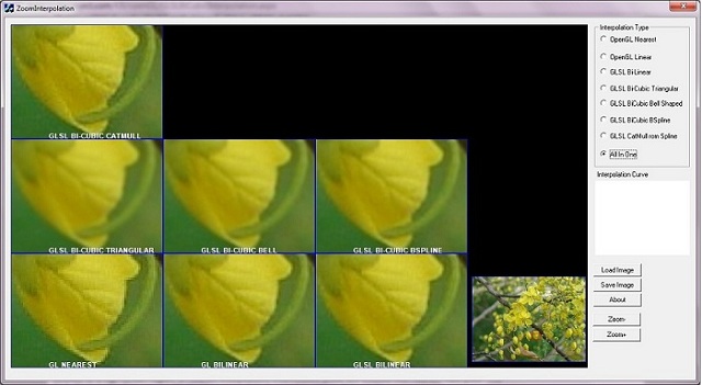
Screenshot of ZoomInterpolationApplication. Small area of flower is zoomed with different interpolations. Different versions of interpolation have quality difference.
of interpolation creates a blocky image, and CatMull-Rom or Bi-Cubic Spline creates a high quality zoomed image. Details of different interpolations are explained in the below sections.
Interpolation is a "Process used to estimate an unknown value between two known values by utilizing a common mathematical relation".
ZoomInterpolationcreates zoomed image with different interpolation types. OpenGL provides a Bi-Linear interpolation at its maximum. When zooming a very small texture area to large area, Bi-Linear provides a less quality.
Bi-Linear interpolation creates an intermediate pixel with the help of nearest 4 pixels. Bi-Cubic interpolation, a high quality version, creates an intermediate pixel with the help of nearest 16 pixels.
is zoomed to a large screen region. In the nearest interpolation, intermediate pixels are created with the nearest valid pixel. This kind of interpolated images are blocky since same data is copied to intermediate pixels.
Below image is created through OpenGL
to be a "stair case". We can remove this stair case through better interpolation methods.

Interpolation with
We can use following code to achieve nearest interpolation in OpenGL fixed function pipeline.

Collapse | Copy
Code
OpenGL provides a good interpolation method,
2 Pixel in Y direction] and create a smooth image comparing to the
interpolates both in X and Y direction. Therefore it is called Bi-Linear interpolation. Details of Bi-Linear interpolation is explained in GLSL
Bi-Linear section.
The following image is created with
through
through the edge of flower, and a small "stair case" is visible at some edges of the flower.

Interpolation with
The following code can be used to achieve Bi-Linear interpolation in OpenGL fixed function pipeline.
Collapse | Copy
Code
OpenGL provides only two interpolations methods to create zoomed display of an image(texture). When zooming a very small region of a texture, we can see some blocky edges in the output image.
The first step to create a better interpolation method is to create Bi-Linear interpolation (which is the same as that of
But we prepare a pixel shader with Bi-Linear interpolation). We can improve the quality of Bi-Linear and get a better quality image.
A pixel shader is a program which will execute for each pixels of a rendering. More details of Pixel Shaders are availablehere or here.
In Bi-Linear interpolation, the nearest four pixels are considered to create an intermediate pixel.

From the above figure, an intermediate pixel F(p’,q’) is created by interpolating nearest four texels F(p,q), F(p,q+1), F(p+1,q), F(p+1,q+1).
Texel is the term used to indicate an element in a texture (similar to a pixel in screen) [A texel, or texture element (also texture pixel) is the fundamental unit of texture space].
Initially two texels in top row and bottom row are interpolated with linear interpolation[horizontal]. Then interpolated pixels of top row and bottom row are also linearly interpolated[vertical]. Explanation with code will help to understand the above description.
An interpolation factor a, is used in X direction to interpolate F(p,q) and F(p,q+1) as follows:
Collapse | Copy
Code
An interpolation factor b, is used in Y direction to interpolate F(p’’) and F(p+1’’) as follows:
Collapse | Copy
Code
Corresponding GLSL shader code.
Collapse | Copy
Code
In the previous method, the nearest four pixels are used to create an intermediate pixel. In this method, the nearest 16 pixels are used to create an intermediate pixel F(p’q’). Therefore the output image quality will increase. In the below figure, an intermediate
pixel F(p'q')[Near to F(p,q)] is created by interpolating nearest 4*4 pixels from F(p-1, q-1) to F(p+2,q+2). Details of this interpolation is explained with the help of code and necessary equations.

The following equation [from Digital Image Processing: PIKS Inside, Third Edition] is used to interpolate nearest 16 pixles. First two sigma(S) are
appeared as 2 for loops in the shader code.

Where F(p+m,q+n) indicates texel data at location (p+m, q+n). Rc() denotes a Bi-Cubic interpolation function such as a BSpline, Traingular, Bell cubic interpolation function. In this sample, I just use a Triangular, Bell,
and B-Spline, andCatMull-Rom interpolation
function.
Following is a GLSL shader code for Bi-Cubic Interpolation:
Collapse | Copy
Code
Nearest 16 texels are iterated through 2 for loops from [x-1,y-1] to [x+2, y+2].
Collapse | Copy
Code
For each nearest element, an interpolation factor is calculated with the corresponding Bi-Cubic interpolation function. In the above
used to get an interpolation factor. Different versions of Bi-Cubic interpolation[BSpline, Traingular, Bell, CatMullRom] can be created by changing
its logic. When plotting values from

From plotting of triangular function, left most value of X axis is
is plotted in Y direction. It indicates
a low input.
For each iteration in
is multiplied with current data. In effect, an intermediate pixel is created by interpolating nearest 16 data. The weightage will be high for nearest pixels, and low for far pixels. The output image of Triangular Bi-Cubic is smoother than Bi-Linear.
Triangular function is a simple Bi-Cubic function, as defined in the following equation:

Here, the return value of R(x) is x+1 when x is between -1 and 0, and return value is x+1 when x is between 0 and 1. The following pseudo code gives more idea of triangular function. This function provides a low value for high input and a high value for a low
input.
Collapse | Copy
Code
The above diagram is the output of
plotted in Y direction.
The following code is used in GLSL shader for Triangular Bi-Cubic implementation.
Collapse | Copy
Code

Interpolation with GLSL Bi-Cubic Triangular interpolation type.
When comparing Bi-Cubic Triangular image with Bi-Linear image, the quality of image is increased. But Triangular creates a blurred effect and all edges are smoothen. The reason of this blurred edge is weight returned from
near and far texel. If weight of near texel is high and far texel is very low, then Bi-Cubic interpolation can achieve smooth edges. Another Bi-Cubic interpolation function which creates a bell shaped (nearest values[Center] are high) and far values are very
low[left and right ends].

The above equation has three conditions to create the following curve. The corresponding code is implemented in
If we plot the input values from
a graph, we will get the following curve. Where X direction contains x provided to
return value[

The above diagram indicates when x is high,
very low weight. For nearest texel
The following code is used in GLSL shader for Bell shaped Bi-Cubic implementation.
Collapse | Copy
Code

Interpolation with Bi-Cubic Bell interpolation type.
When comparing Bi-Cubic Bell shaped with B spline, interpolated image is smooth and edges are more clear. The below equation is used to create

The code of this equation is implemented in

The above diagram is the output of
plotted in Y direction. x starts from -2.0 and ends at +2.0. It indicates when x is high,
therefore far data of an intermediate texel gets very lower weight. When comparing to Bell shaped wave, values in far range (near
are very low. Therefore, the final output image is also smoother than Bell Bi-Cubic interpolated image. The following code is used in GLSL shader for BSpline implementation.
Collapse | Copy
Code

Interpolation with Bi-Cubic BSpline interpolation type.
All above Bi-Cubic methods creates a blurred(or smooth) effect. After applying the above interpolation methods, the edges of image become smooth. This method(CatMull-Rom method) preserves edges of image. The following equation is used to create
which is used in GLSL shader for

This equation is available in Reconstruction
Filters in Computer Graphics [Equation 8]. If we replace B with 0.0 and C with 0.5, this equation provides
interpolation values. The following code is used in GLSL shader for CatMul-Rom implementation.
Collapse | Copy
Code

The interpolation curve of
data gets high weight to multiply, but far data gets negative value. Therefore, the effect of far data will be removed in the intermediate pixel.
a texture with a bitmap [Flower.bmp] available in the resource of this application.
Collapse | Copy
Code
This application displays two images, zoomed image is in left, and actual image is at right bottom area. Two viewports are used for displaying actual image and zoomed image. A red rectangle indicates zoomed image. Small area of image is selected for texture
mapping and displayed to screen.
The following code is used to draw the actual image with a RED rectangle indicating zoomed image area.
Collapse | Copy
Code
The following code is used to create the zoomed image with current interpolation.
Collapse | Copy
Code
In
displays zoomed image, and second display is a miniature of actual image.
different image display area, zoomed image and miniature of actual image.
zoom and unzoom. Two buttons “Zoom+” and “Zoom-“ are also added to increase zoom or decrease zoom.
will be displayed.
supports different image extensions such as .bmp, .jpg, .png, .tga,
etc.
this article, to save the zoomed image into a bmp or jpeg file. "Save Image" button is added in
to save zoomed area to a bitmap file. Save operation is also supported in "All in one View". Pixel information is read from the rendering window, and saved to a BMP file using
is used to read pixel information from rendering window.
The following code is used to retrieve pixel information from rendering area, and to save as a bmp file.
Collapse | Copy
Code
This graphical representation helps to identify the weight applied to nearest pixels and far pixels. In X direction, the distance is shown. In Y direction, the weight for a distance is shown. In all Bi-Cubic functions, higher weight is applied to very nearest
pixel(When distance is 0). The weight decreases on increasing the distance.
file. This class supports bmp, jpg, png, and tga format files. GDI+ classes are used to load different image file formats.
shader.
opengl initialisations.
a Quad image with texture mapping.
the help of GDI.
All mouse move and button handling are implemented in this class. All other classes in this application are used in this class.
image in a single frame.
view. This class uses
in this article, to prepare a combined image view of different type of interpolations. This type of view helps to compare different interpolations. We can compare quality of different interpolation methods with a single image. I just prepared a class
display zoomed image in a particular window area. 7 objects of
Linear, GLSL BiCubic Triangular etc.. ] are provided to these
is used to display interpolation type in image area. Thanks to dan.g., for his suggestion,
which helps me to create such a view.
Code to prepare different type of interpolations.
Collapse | Copy
Code
The input image is expected in an aspect ratio of 4:3 for better output image. Otherwise stretched/skewed image will be displayed.
For GLSL shader implementation, following OpenGL extensions are required in your machine.
a.
b.
If your machine does-not have a supporting graphics device, this application will display interpolation with openGL fixed function pipeline(Nearest and Linear).
The shaders for different Bi-Cubic and Bi-Linear interpolation is prepared with the help some equations, I expect some issues in this code.

4.3. Image Reconstruction Systems.
13.5.1. Interpolation Methods
http://www.cambridgeincolour.com/tutorials/image-interpolation.htm
http://en.wikipedia.org/wiki/Bilinear_interpolation
http://en.wikipedia.org/wiki/Bicubic_interpolation
Reconstruction Filters in Computer Graphics http://www.mentallandscape.com/Papers_siggraph88.pdf
08-Aug-2011: Added details of
21-Aug-2011: Added CatMull-Rom interpolation, Interpolation curve with Range values
26-Aug-2011: Created "All In One" View. Created outline for zoomed and actual image display
30-Aug-2011: Added "Save Image" functionality
Table Of Contents
IntroductionBackground
OpenGL
Nearest Interpolation
OpenGL
Linear Interpolation
GLSL
Bi-Linear
GLSL
Bi-Cubic
Triangular
Bell
B
Spline
CatMull-Rom
ZoomInterpolation
Application
All
in One View
Limitations
References
Revision
History
Introduction
In OpenGL, we can display a texture to small or large area. Displaying a texture in the same size requires copying all texels (texture units) to output pixels. If we want to create a large image from a small texture, OpenGL has to create many intermediate pixels.This process of creating intermediate pixels is called as Interpolation.
OpenGL provides two interpolation methods to create a large texture image.
GL_NEARESTand
GL_LINEAR.
We can provide
GL_NEARESTor
GL_LINEARas
GL_TEXTURE_MAG_FILTERparameter
for
glTexParameterf()function.
GL_NEARESTis
a low quality interpolation and
GL_LINEARprovides Bi-Linear interpolation. In addition to OpenGL interpolation types,
here different versions of Bi-Cubic interpolation are implemented in pixel shaders. Bi-Cubic interpolation can provide good quality image on creating large image from small textures.
Screenshot of ZoomInterpolationApplication. Small area of flower is zoomed with different interpolations. Different versions of interpolation have quality difference.
GL_NEARESTtype
of interpolation creates a blocky image, and CatMull-Rom or Bi-Cubic Spline creates a high quality zoomed image. Details of different interpolations are explained in the below sections.
Background
Interpolation is a "Process used to estimate an unknown value between two known values by utilizing a common mathematical relation".ZoomInterpolationcreates zoomed image with different interpolation types. OpenGL provides a Bi-Linear interpolation at its maximum. When zooming a very small texture area to large area, Bi-Linear provides a less quality.
Bi-Linear interpolation creates an intermediate pixel with the help of nearest 4 pixels. Bi-Cubic interpolation, a high quality version, creates an intermediate pixel with the help of nearest 16 pixels.
OpenGL GL_NEARESTInterpolation
GL_NEARESTjust copies data available in the nearest pixel and it creates a blocky effect when a very small region
is zoomed to a large screen region. In the nearest interpolation, intermediate pixels are created with the nearest valid pixel. This kind of interpolated images are blocky since same data is copied to intermediate pixels.
Below image is created through OpenGL
GL_NEARESTinterpolation and its quality is very bad. Edge of the flower seems
to be a "stair case". We can remove this stair case through better interpolation methods.
Interpolation with
GL_NEARESTinterpolation type.
We can use following code to achieve nearest interpolation in OpenGL fixed function pipeline.
Collapse | Copy
Code
glTexParameteri( GL_TEXTURE_2D,GL_TEXTURE_MAG_FILTER, GL_NEAREST);
glTexParameteri( GL_TEXTURE_2D,GL_TEXTURE_MIN_FILTER, GL_NEAREST);
OpenGL GL_LINEARInterpolation
OpenGL provides a good interpolation method, GL_LINEAR. It interpolates nearest 4 pixels[2 pixel in X direction and
2 Pixel in Y direction] and create a smooth image comparing to the
GL_NEARESTmethod.
GL_LINEARmethod
interpolates both in X and Y direction. Therefore it is called Bi-Linear interpolation. Details of Bi-Linear interpolation is explained in GLSL
Bi-Linear section.
The following image is created with
GL_LINEARinterpolation and its edges are smooth when comparing to the image created
through
GL_NEARESTinterpolation. Here "stair case" effect is not visible. But we can see a shade of yellow and green
through the edge of flower, and a small "stair case" is visible at some edges of the flower.
Interpolation with
GL_LINEARinterpolation type.
The following code can be used to achieve Bi-Linear interpolation in OpenGL fixed function pipeline.
Collapse | Copy
Code
glTexParameteri( GL_TEXTURE_2D,GL_TEXTURE_MAG_FILTER, GL_LINEAR);
glTexParameteri( GL_TEXTURE_2D,GL_TEXTURE_MIN_FILTER, GL_LINEAR);
GLSL Bi-Linear
OpenGL provides only two interpolations methods to create zoomed display of an image(texture). When zooming a very small region of a texture, we can see some blocky edges in the output image.The first step to create a better interpolation method is to create Bi-Linear interpolation (which is the same as that of
GL_LINEARinterpolation.
But we prepare a pixel shader with Bi-Linear interpolation). We can improve the quality of Bi-Linear and get a better quality image.
A pixel shader is a program which will execute for each pixels of a rendering. More details of Pixel Shaders are availablehere or here.
Bi-Linear Shader Implementation
In Bi-Linear interpolation, the nearest four pixels are considered to create an intermediate pixel.From the above figure, an intermediate pixel F(p’,q’) is created by interpolating nearest four texels F(p,q), F(p,q+1), F(p+1,q), F(p+1,q+1).
Texel is the term used to indicate an element in a texture (similar to a pixel in screen) [A texel, or texture element (also texture pixel) is the fundamental unit of texture space].
Initially two texels in top row and bottom row are interpolated with linear interpolation[horizontal]. Then interpolated pixels of top row and bottom row are also linearly interpolated[vertical]. Explanation with code will help to understand the above description.
An interpolation factor a, is used in X direction to interpolate F(p,q) and F(p,q+1) as follows:
Collapse | Copy
Code
F(p’’) = (1.0 – a ) * F(p,q) + a * F(p+1, q) // Linear interpolation in X direction[Top].
F(p+1’’) = (1.0 – a ) * F(p,q+1) + a * F(p+1, q+1) 	// Linear interpolation in
// X direction[Bottom].
An interpolation factor b, is used in Y direction to interpolate F(p’’) and F(p+1’’) as follows:
Collapse | Copy
Code
F(p’,q’) = (1.0 - b) * F(p’’) + b * F(p+1’’) // Linear interpolation in Y direction.
Corresponding GLSL shader code.
Collapse | Copy
Code
// Function to get interpolated texel data from a texture with GL_NEARESTproperty.
// Bi-Linear interpolation is implemented in this function with the
// help of nearest four data.
vec4 tex2DBiLinear( sampler2D textureSampler_i, vec2 texCoord_i )
{
vec4 p0q0 = texture2D(textureSampler_i, texCoord_i);
vec4 p1q0 = texture2D(textureSampler_i, texCoord_i + vec2(texelSizeX, 0));

vec4 p0q1 = texture2D(textureSampler_i, texCoord_i + vec2(0, texelSizeY));
vec4 p1q1 = texture2D(textureSampler_i, texCoord_i + vec2(texelSizeX , texelSizeY));

float a = fract( texCoord_i.x * fWidth ); // Get Interpolation factor for X direction.
// Fraction near to valid data.

vec4 pInterp_q0 = mix( p0q0, p1q0, a ); // Interpolates top row in X direction.
vec4 pInterp_q1 = mix( p0q1, p1q1, a ); // Interpolates bottom row in X direction.

float b = fract( texCoord_i.y * fHeight );// Get Interpolation factor for Y direction.
return mix( pInterp_q0, pInterp_q1, b ); // Interpolate in Y direction.
}
GLSL Bi-Cubic
In the previous method, the nearest four pixels are used to create an intermediate pixel. In this method, the nearest 16 pixels are used to create an intermediate pixel F(p’q’). Therefore the output image quality will increase. In the below figure, an intermediatepixel F(p'q')[Near to F(p,q)] is created by interpolating nearest 4*4 pixels from F(p-1, q-1) to F(p+2,q+2). Details of this interpolation is explained with the help of code and necessary equations.
The following equation [from Digital Image Processing: PIKS Inside, Third Edition] is used to interpolate nearest 16 pixles. First two sigma(S) are
appeared as 2 for loops in the shader code.
Where F(p+m,q+n) indicates texel data at location (p+m, q+n). Rc() denotes a Bi-Cubic interpolation function such as a BSpline, Traingular, Bell cubic interpolation function. In this sample, I just use a Triangular, Bell,
and B-Spline, andCatMull-Rom interpolation
function.
Following is a GLSL shader code for Bi-Cubic Interpolation:
Collapse | Copy
Code
vec4 BiCubic( sampler2D textureSampler, vec2 TexCoord )
{
float texelSizeX = 1.0 / fWidth; //size of one texel
float texelSizeY = 1.0 / fHeight; //size of one texel
vec4 nSum = vec4( 0.0, 0.0, 0.0, 0.0 );
vec4 nDenom = vec4( 0.0, 0.0, 0.0, 0.0 );
float a = fract( TexCoord.x * fWidth ); // get the decimal part
float b = fract( TexCoord.y * fHeight ); // get the decimal part
for( int m = -1; m <=2; m++ )
{
for( int n =-1; n<= 2; n++)
{
vec4 vecData = texture2D(textureSampler,
TexCoord + vec2(texelSizeX * float( m ),
texelSizeY * float( n )));
float f  = Triangular( float( m ) - a );
vec4 vecCooef1 = vec4( f,f,f,f );
float f1 = Triangular ( -( float( n ) - b ) );
vec4 vecCoeef2 = vec4( f1, f1, f1, f1 );
nSum = nSum + ( vecData * vecCoeef2 * vecCooef1  );
nDenom = nDenom + (( vecCoeef2 * vecCooef1 ));
}
}
return nSum / nDenom;
}BiCubic()function gets a texture coordinate (x,y) and returns the interpolated value of nearest 16 texels.
Nearest 16 texels are iterated through 2 for loops from [x-1,y-1] to [x+2, y+2].
Collapse | Copy
Code
for( int m = -1; m <=2; m++ )
{
for( int n =-1; n<= 2; n++)
For each nearest element, an interpolation factor is calculated with the corresponding Bi-Cubic interpolation function. In the above
BiCubic()function
Triangular()is
used to get an interpolation factor. Different versions of Bi-Cubic interpolation[BSpline, Traingular, Bell, CatMullRom] can be created by changing
Triangular()and
its logic. When plotting values from
Triangular(), we will get the below image in a triangle form:
From plotting of triangular function, left most value of X axis is
-2and right most value of X axis is
+2.
Triangular(x)
is plotted in Y direction. It indicates
Triangularfunction returns lower value for a high input and high value for
a low input.
For each iteration in
BiCubic(), return value of
Triangular()
is multiplied with current data. In effect, an intermediate pixel is created by interpolating nearest 16 data. The weightage will be high for nearest pixels, and low for far pixels. The output image of Triangular Bi-Cubic is smoother than Bi-Linear.
Implementation of Bi-Cubic Interpolation[ Triangular ]
Triangular function is a simple Bi-Cubic function, as defined in the following equation:Here, the return value of R(x) is x+1 when x is between -1 and 0, and return value is x+1 when x is between 0 and 1. The following pseudo code gives more idea of triangular function. This function provides a low value for high input and a high value for a low
input.
Collapse | Copy
Code
if( -1 < x && x <= 0 )
{
return x + 1
}
else if( 0 < x && x <= 1 )
{
return x - 1
}
The above diagram is the output of
Triangular()function.
Triangular(x)is
plotted in Y direction.
The following code is used in GLSL shader for Triangular Bi-Cubic implementation.
Collapse | Copy
Code
float Triangular( float f )
{
f = f / 2.0;
if( f < 0.0 )
{
return ( f + 1.0 );
}
else
{
return ( 1.0 - f );
}
return 0.0;
}
Interpolation with GLSL Bi-Cubic Triangular interpolation type.
Implementation of Bi-Cubic Interpolation[ Bell ]
When comparing Bi-Cubic Triangular image with Bi-Linear image, the quality of image is increased. But Triangular creates a blurred effect and all edges are smoothen. The reason of this blurred edge is weight returned fromTriangular()for
near and far texel. If weight of near texel is high and far texel is very low, then Bi-Cubic interpolation can achieve smooth edges. Another Bi-Cubic interpolation function which creates a bell shaped (nearest values[Center] are high) and far values are very
low[left and right ends].
The above equation has three conditions to create the following curve. The corresponding code is implemented in
BellFunc().
If we plot the input values from
-2to
+2of
BellFunc()in
a graph, we will get the following curve. Where X direction contains x provided to
BellFuncand Y direction is corresponding
return value[
BellFunc(x)].
The above diagram indicates when x is high,
BellFunc(x)is very low, therefore far data of an intermediate texel gets
very low weight. For nearest texel
BellFunc(x)is high and gets a high weight.
The following code is used in GLSL shader for Bell shaped Bi-Cubic implementation.
Collapse | Copy
Code
float BellFunc( float x )
{
float f = ( x / 2.0 ) * 1.5; // Converting -2 to +2 to -1.5 to +1.5
if( f > -1.5 && f < -0.5 )
{
return( 0.5 * pow(f + 1.5, 2.0));
}
else if( f > -0.5 && f < 0.5 )
{
return 3.0 / 4.0 - ( f * f );
}
else if( ( f > 0.5 && f < 1.5 ) )
{
return( 0.5 * pow(f - 1.5, 2.0));
}
return 0.0;
}
Interpolation with Bi-Cubic Bell interpolation type.
Implementation of Bi-Cubic Interpolation[ B-Spline ]
When comparing Bi-Cubic Bell shaped with B spline, interpolated image is smooth and edges are more clear. The below equation is used to create BSpline()function.
The code of this equation is implemented in
BSpline()function.
The above diagram is the output of
BSpline()function.
BSpline(x)is
plotted in Y direction. x starts from -2.0 and ends at +2.0. It indicates when x is high,
BSpline(x)is very low and
therefore far data of an intermediate texel gets very lower weight. When comparing to Bell shaped wave, values in far range (near
-2and
+2)
are very low. Therefore, the final output image is also smoother than Bell Bi-Cubic interpolated image. The following code is used in GLSL shader for BSpline implementation.
Collapse | Copy
Code
float BSpline( float x )
{
float f = x;
if( f < 0.0 )
{
f = -f;
}

if( f >= 0.0 && f <= 1.0 )
{
return ( 2.0 / 3.0 ) + ( 0.5 ) * ( f* f * f ) - (f*f);
}
else if( f > 1.0 && f <= 2.0 )
{
return 1.0 / 6.0 * pow( ( 2.0 - f  ), 3.0 );
}
return 1.0;
}
Interpolation with Bi-Cubic BSpline interpolation type.
Implementation of Bi-Cubic Interpolation[CatMull-Rom]
All above Bi-Cubic methods creates a blurred(or smooth) effect. After applying the above interpolation methods, the edges of image become smooth. This method(CatMull-Rom method) preserves edges of image. The following equation is used to create CatMullRom()function,
which is used in GLSL shader for
CatMullRominterpolation.
This equation is available in Reconstruction
Filters in Computer Graphics [Equation 8]. If we replace B with 0.0 and C with 0.5, this equation provides
CatMul-Rom
interpolation values. The following code is used in GLSL shader for CatMul-Rom implementation.
Collapse | Copy
Code
float CatMullRom( float x )
{
const float B = 0.0;
const float C = 0.5;
float f = x;
if( f < 0.0 )
{
f = -f;
}
if( f < 1.0 )
{
return ( ( 12 - 9 * B - 6 * C ) * ( f * f * f ) +
( -18 + 12 * B + 6 *C ) * ( f * f ) +
( 6 - 2 * B ) ) / 6.0;
}
else if( f >= 1.0 && f < 2.0 )
{
return ( ( -B - 6 * C ) * ( f * f * f )
+ ( 6 * B + 30 * C ) * ( f *f ) +
( - ( 12 * B ) - 48 * C  ) * f +
8 * B + 24 * C)/ 6.0;
}
else
{
return 0.0;
}
}
The interpolation curve of
CatMullRom is little different with other Bi-Cubic interpolation curves. Here very near
data gets high weight to multiply, but far data gets negative value. Therefore, the effect of far data will be removed in the intermediate pixel.
About ZoomInterpolationApplication
ZoomInterpolationis an application created to demonstrate different interpolation methods. On startup, it creates
a texture with a bitmap [Flower.bmp] available in the resource of this application.
Collapse | Copy
Code
BMPLoader BMPLoadObj; // To load an RGB of a bmp file
BYTE* pbyData = 0;
BMPLoadObj.LoadBMP( IDB_BITMAP_FLOWER, m_nImageWidth, m_nImageHeight, pbyData );
m_glTexture.Create( m_nImageWidth, m_nImageHeight, pbyData );// Texture creating with bmp
This application displays two images, zoomed image is in left, and actual image is at right bottom area. Two viewports are used for displaying actual image and zoomed image. A red rectangle indicates zoomed image. Small area of image is selected for texture
mapping and displayed to screen.
The following code is used to draw the actual image with a RED rectangle indicating zoomed image area.
Collapse | Copy
Code
/*
This function draws miniature of actual image with a Red region
indicating the zoomed area.
*/
void CZoomInterpolationDlg::DrawActualImage()
{
// Set Rendering area of Actual image.
glViewport( 805, 10, 200, 150 );

// Image is attached.
m_glTexture.Enable();

// Entire image is mapped to screen.
m_glVertexBuffer.DrawVertexBuffer( GL_QUADS );
m_glTexture.Disable();

// Set Red color for Zoom area indication.
glColor3f( 1.0, 0.0, 0.0 );

float fXStart = m_fXOffset * 2;
float fYStart = m_fYOffset * 2;
float fWidth = m_fZoomWidth * 2;
float fHeight = m_fZoomHeight * 2;

// Draw a rectangle indicate zoom area.
glBegin( GL_LINE_LOOP );
glVertex2d( -1.0 + fXStart         ,  -1.0 + fYStart );
glVertex2d( -1.0 + fXStart + fWidth,  -1.0 + fYStart );
glVertex2d( -1.0 + fXStart + fWidth,  -1.0 + fYStart + fHeight );
glVertex2d( -1.0 + fXStart         ,  -1.0 + fYStart + fHeight );
glVertex2d( -1.0 + fXStart         ,  -1.0 + fYStart );
glColor3f( 1.0, 1.0, 1.0 );
glEnd();
}
The following code is used to create the zoomed image with current interpolation.
Collapse | Copy
Code
/*
Creating zoomed image.
*/
void CZoomInterpolationDlg::DrawZoomedImage()
{
// Displays all views. Draw()_ method of GLImageViewprepares the
// Zoomed image of a view. m_ImageView list holds single object in normal case.
// When All In View is selected in Interpolation type, m_ImageView will hold 7 View
// objects.
for( int nViewIndex = 0; nViewIndex < m_ImageView.size(); nViewIndex++ )
{
(m_ImageView[nViewIndex])->Draw();
}
}
In
ZoomInterpolationa rendering area is prepared, then set two viewports to display two types images. First one
displays zoomed image, and second display is a miniature of actual image.
glViewport()calls at the first step of
CZoomInterpolationDlg::DrawActualImage()and
CZoomInterpolationDlg::DrawZoomedImage)prepares
different image display area, zoomed image and miniature of actual image.
Pan operation
When mouse clicks on zoomed image and pans, the texture mapping region changes with respect to mouse move and it creates a pan effect.Zoom and UnZoom
When Mouse scrolls, the zoom/unzoom is implemented by increasing or decreasing the texture mapping area.CZoomInterpolationDlg::HandleZoom()handles
zoom and unzoom. Two buttons “Zoom+” and “Zoom-“ are also added to increase zoom or decrease zoom.
Loading new Image
A button “Load Image” is available to load an image file from your machine. The image area is created in an aspect ratio of 4:3[800X600 pixels]. Therefore input image is expected in an aspect ratio of 4:3 for better quality. Otherwise stretched/skewed imagewill be displayed.
BMPLoaderclass is used to retrieve RGB data from bitmap with the help of Gdi+ library. This class
supports different image extensions such as .bmp, .jpg, .png, .tga,
etc.
Save Zoomed Image
_rps added a comment inthis article, to save the zoomed image into a bmp or jpeg file. "Save Image" button is added in
ZoomInterpolationapplication
to save zoomed area to a bitmap file. Save operation is also supported in "All in one View". Pixel information is read from the rendering window, and saved to a BMP file using
BMPLoaderclass.
glReadPixels()API
is used to read pixel information from rendering window.
The following code is used to retrieve pixel information from rendering area, and to save as a bmp file.
Collapse | Copy
Code
void CZoomInterpolationDlg::OnBnClickedButtonSave()
{
CString csFileName;
csFileName.Format( L"ZoomInterpolation.bmp" );
CFileDialog SaveDlg( false, L"*.bmp", csFileName );
if( IDOK == SaveDlg.DoModal())
{
RECT stImageArea;
stImageArea.left =0;
stImageArea.top = 0;
stImageArea.right = 800;
stImageArea.bottom = 600;
CString csFileName = SaveDlg.GetPathName();
BYTE* pbyData = new BYTE[stImageArea.bottom * stImageArea.right  * 3];
if( 0 == pbyData )
{
AfxMessageBox( L"Memory Allocation failed" );
return;
}
glReadPixels( 0, 0, stImageArea.right, stImageArea.bottom,
GL_BGR_EXT, GL_UNSIGNED_BYTE, pbyData );
BMPLoader SaveBmp;
SaveBmp.SaveBMP( csFileName, stImageArea.right, stImageArea.bottom, pbyData );
delete[] pbyData;
}
}
Plotting of Interpolation Curve
A simple class is created to plot the curve indicating weights applied in Bi-Cubic interpolation function. Triangular, Bell, and BSpline are plotted with the same code of GLSL shader code. This plotting shows minimum and maximum values in X, and Y direction.This graphical representation helps to identify the weight applied to nearest pixels and far pixels. In X direction, the distance is shown. In Y direction, the weight for a distance is shown. In all Bi-Cubic functions, higher weight is applied to very nearest
pixel(When distance is 0). The weight decreases on increasing the distance.
Main Classes Used in ZoomInterpolationApplication
BMPLoader: This class is used for getting RGB information of an image
file. This class supports bmp, jpg, png, and tga format files. GDI+ classes are used to load different image file formats.
GLExtension: This class holds all opengl extensions required for pixel
shader.
GLSetup: This class is used for creating a rendering context and other
opengl initialisations.
GLVertexBuffer: This class holds vertex data required for rendering
a Quad image with texture mapping.
PlotInterpCurve: This class draws current interpolation curve with
the help of GDI.
ZoomInterpolationDlg: This class handles the main operations of
ZoomInterpolationApplication.
All mouse move and button handling are implemented in this class. All other classes in this application are used in this class.
GLImageView: This class introduced to create different interpolated
image in a single frame.
GLText: This class is used to display text display in "All In One"
view. This class uses
FontEngineclass.
All In One View
dan.g. added a commentin this article, to prepare a combined image view of different type of interpolations. This type of view helps to compare different interpolations. We can compare quality of different interpolation methods with a single image. I just prepared a class
GLImageViewto
display zoomed image in a particular window area. 7 objects of
GLImageViewclass are created, different shader programs[GLSL
Linear, GLSL BiCubic Triangular etc.. ] are provided to these
GLImageViewobjects to achieve different types of interpolations.
GLTextclass
is used to display interpolation type in image area. Thanks to dan.g., for his suggestion,
which helps me to create such a view.
Code to prepare different type of interpolations.
Collapse | Copy
Code
void CZoomInterpolationDlg::PrepareAllInOneView()
{
...............

int nViewPortXDiv = 800 / 3;
int nViewPortYDiv = 600 / 3;
int nResourceId = IDR_GLSL_SHADER_BILINEAR;

for( int nI = 0; nI < 7; nI++ )
{
int nX = nI % 3;
int nY = nI / 3;

GLText* pText = new GLText( &m_FontEngine );
pText->SetText( INTERPOLATION_NAMES[nI] );

GLImageView* pImage = new GLImageView();
pImage->SetViewport( nX * nViewPortXDiv, nY * nViewPortYDiv,
nViewPortXDiv, nViewPortYDiv );
pImage->SetText( pText );
GLenum eTextureFilter;
if( nI >= 2 )
{
GLSLShader* pTempShader = new GLSLShader();

pTempShader->CreateProgram( nResourceId++, GL_FRAGMENT_PROGRAM_ARB );
pImage->SetShader( pTempShader, true );
eTextureFilter = GL_NEAREST;
}
else
{
pImage->SetShader( 0 ); // Shader is not required for openGL interpolation
if( 0 == nI )
{
eTextureFilter = GL_NEAREST; // Special Handling for OpenGL Interpolation
}
else
{
eTextureFilter = GL_LINEAR;  // Special Handling for OpenGL Interpolation
}
}
pImage->SetTextureParam( &m_glTexture, m_nImageWidth,
m_nImageHeight, eTextureFilter );
pImage->SetVertexBuffer( &m_glVertexBufferZoom );
m_ImageView.push_back( pImage );
}
}
Limitations
The input image is expected in an aspect ratio of 4:3 for better output image. Otherwise stretched/skewed image will be displayed.For GLSL shader implementation, following OpenGL extensions are required in your machine.
a.
GL_ARB_fragment_shader
b.
GL_ARB_vertex_shader
If your machine does-not have a supporting graphics device, this application will display interpolation with openGL fixed function pipeline(Nearest and Linear).
The shaders for different Bi-Cubic and Bi-Linear interpolation is prepared with the help some equations, I expect some issues in this code.
References
Digital Image Processing: PIKS Inside, Third Edition. William K. Pratt[ISBN: 0-471-22132-5] Section:4.3. Image Reconstruction Systems.
13.5.1. Interpolation Methods
http://www.cambridgeincolour.com/tutorials/image-interpolation.htm
http://en.wikipedia.org/wiki/Bilinear_interpolation
http://en.wikipedia.org/wiki/Bicubic_interpolation
Reconstruction Filters in Computer Graphics http://www.mentallandscape.com/Papers_siggraph88.pdf
Revision History
07-Aug-2011: Initial version08-Aug-2011: Added details of
ZoomInterpolationapplication
21-Aug-2011: Added CatMull-Rom interpolation, Interpolation curve with Range values
26-Aug-2011: Created "All In One" View. Created outline for zoomed and actual image display
30-Aug-2011: Added "Save Image" functionality

相关文章推荐
- 《Zoom An Image With Different Interpolation Types》
- How to rotate an image with CSS under different browser
- An App ID with Identifier is not available. Please enter a different string
- OpenCV.2.Computer.Vision.Application.Programming.Cookbook--Scanning an image with pointers
- How to mount an ISO Image with AIX 6.1 TL4
- Preloading an Image with jQuery--reference
- iOS打开旧项目报错:Typedef redefinition with different types (‘SCNetworkConnectionFlags’ (aka ‘unsigned int
- Java出现No enclosing instance of type ImageViewer is accessible. Must qualify the allocation with an
- Effects with the Pixel Bender Toolkit – Part 5: Applying a filter to an image in Flash
- BadImageFormatException or An attempt was made to load a program with an incorrect format
- An iterative image registration technique with an application to stereo vision笔记
- (C#) System.BadImageFormatException: An attempt was made to load a program with an incorrect format.
- [Yii Framework] How to develop an extension with image, css and js
- Running an application command line with different credentials
- Deep Zoom Image Generation with DeepZoomTools.DLL
- NavigationBar ( with an image )
- [Generic] Creating an image format with an unknown type is an error
- get an image file with XMLHttpRequest and encode with base64
- An App ID with Identifier 'com.FE.BMH' is not available. Please enter a different string.
- 解决 an app id with identifier is not available. please enter a different string. xcode 7.3