Silverlight学习笔记--SilverLight中的基本图形
2010-10-28 16:38
561 查看
1. 先写一个页面文件 test.html
2. 然后写xaml文件, mytest.xaml,以后更改这个文件看效果就行了, 如下:
3. 矩形(Rectangle)
矩形除了上面的几个属性外,还可以设置圆角矩形。
4. 椭圆(Ellipse)
椭圆和矩形没有什么本质区别,只是为了设置更方便,将RadiusX和RadiusY设为长或宽的一半。
因此椭圆就是比矩形少两个属性,不用再设置RadiusX和RadiusY了。这里就不抓图了。
5. 多边形 (Polygon)
多边形当然就是需要指定多条线,因此多了一个Points属性,指定每个点,同时Fill, Stroke, StrokeThickness都可用。
当在Canvas中时,如果不指定Canvas.Top和Canvas.Left,则起始点是基于Canvas的0,0点,否则基于指定的点。
6. 线段(Line)
线当然需要指定起点和终点,这就多了X1,Y1,X2,Y2四个属性,同时还可以指定两个端点的样式,如方的,圆的,三角
的之类的。也就又多了两个属性,StrokeStartLineCap和StrokeEndLineCap。此外还有Stroke和StrokeThickness.
7. 多线段
这个跟Polygon基本一样,只是最后一个点与第一个点不一样,就不会封闭。如:
8. 路径(Path)
路径用来表示比较复杂的图形。前面的几种图形它都能表示,同时还可以表示各种复杂曲线图形。
Path主要使用Data属性来表示图形。Data里面指定命令,M表示移动到,L表示画直线到,V表示画垂直线到,
H表示画水平线到,Z表示结束(直接到起始点),C表示三次贝塞尔曲线,Q表示两次贝塞尔曲线,
S表示平滑的贝塞尔曲线,A表示曲线,具体就需要看看帮助文档了。
如下,先移动到50,50,再画线到100,100,再画线到200,10,再横向画到150,再纵向画到90,再结束。
路径中的Data属性还可以设置一些几何形状,如RectangleGeometry, EllipseGeometry, LineGeometry, PathGeometry等等。
如:
如果有多个形状,需要放到GeometryGroup中。
几何形状与上面的图形的区别主要在于几何形状完全是数学描述,不涉及显示相关,也就没有Fill, Stroke之类的属性。
9. 其它几个常用的相关属性
StrokDashArray: 画虚线用。里面放着短线和空格的宽度,如奇数位代表短线,偶数位代表空格。
如:StrokeDashArray=”2,1”, 代表短线为2,空格为1
StrokeLineJoin: 线连接,可以设为Miter, Round, Bevel.
StrokeMiterLimit: 线延伸时的限值。
Visibility: 可视。可以设为Visible或Collapsed. 当设为Collapsed时,不能接收输入事件。
Opacity:透明度。0到1之间的任何值。0表示完全透明。当设为0时,可以接收输入事件。
Stretch: 伸缩。可以设为None,Uniform, UniformToFill。主要是当图形填充为图像,画刷或媒体时用。
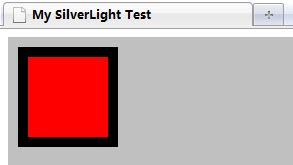
<html>
<head>
<title>My SilverLight Test</title>
</head>
<body>
<object type="application/x-silverlight-2" id="mySL"
width="800" height="600">
<param name="background" value="silver" />
<param name="source" value="mytest.xaml" />
</object>
</body>
</html>
2. 然后写xaml文件, mytest.xaml,以后更改这个文件看效果就行了, 如下:
<Canvas
xmlns="http://schemas.microsoft.com/winfx/2006/xaml/presentation"
xmlns:x="http://schemas.microsoft.com/winfx/2006/xaml">
<Rectangle Canvas.Top="10" Canvas.Left="10"
Width="100" Height="100" Fill="Red" Stroke="Black" StrokeThickness="10"/>
</Canvas>
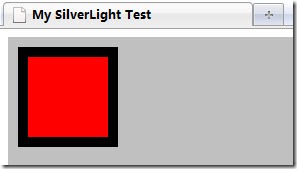
这样,Html页面中设置了SilverLight控件的大小是800X600,背景色是银灰色。而xaml文件就是我们的内容。
内容使用Canvas作为布局控件,现在在其中放置了一个矩形图形,位于左上角10,10的位置,宽度和高度都是
100, 红色背景,边线是黑色,边线线宽为10.如下:
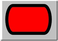
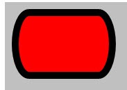
3. 矩形(Rectangle)
矩形除了上面的几个属性外,还可以设置圆角矩形。
<Canvas
xmlns="http://schemas.microsoft.com/winfx/2006/xaml/presentation"
xmlns:x="http://schemas.microsoft.com/winfx/2006/xaml">
<Rectangle Canvas.Top="10" Canvas.Left="10"
Width="150" Height="100" Fill="Red" Stroke="Black" StrokeThickness="10"
RadiusX="20" RadiusY="50"/>
</Canvas>
4. 椭圆(Ellipse)
椭圆和矩形没有什么本质区别,只是为了设置更方便,将RadiusX和RadiusY设为长或宽的一半。
因此椭圆就是比矩形少两个属性,不用再设置RadiusX和RadiusY了。这里就不抓图了。
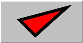
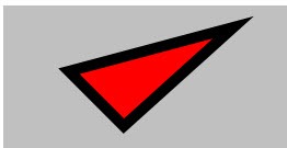
5. 多边形 (Polygon)
多边形当然就是需要指定多条线,因此多了一个Points属性,指定每个点,同时Fill, Stroke, StrokeThickness都可用。
当在Canvas中时,如果不指定Canvas.Top和Canvas.Left,则起始点是基于Canvas的0,0点,否则基于指定的点。
<Canvas
xmlns="http://schemas.microsoft.com/winfx/2006/xaml/presentation"
xmlns:x="http://schemas.microsoft.com/winfx/2006/xaml">
<Polygon Canvas.Top="10" Canvas.Left="10"
Fill="Red" Stroke="Black" StrokeThickness="10"
Points="50,50 100,100 200,10"/>
</Canvas>
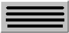
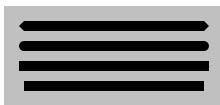
6. 线段(Line)
线当然需要指定起点和终点,这就多了X1,Y1,X2,Y2四个属性,同时还可以指定两个端点的样式,如方的,圆的,三角
的之类的。也就又多了两个属性,StrokeStartLineCap和StrokeEndLineCap。此外还有Stroke和StrokeThickness.
<Canvas
xmlns="http://schemas.microsoft.com/winfx/2006/xaml/presentation"
xmlns:x="http://schemas.microsoft.com/winfx/2006/xaml">
<Line X1="20" Y1="20" X2="200" Y2="20" Stroke="Black" StrokeThickness="10"
StrokeStartLineCap="Triangle" StrokeEndLineCap="Triangle"/>
<Line X1="20" Y1="40" X2="200" Y2="40" Stroke="Black" StrokeThickness="10"
StrokeStartLineCap="Round" StrokeEndLineCap="Round"/>
<Line X1="20" Y1="60" X2="200" Y2="60" Stroke="Black" StrokeThickness="10"
StrokeStartLineCap="Square" StrokeEndLineCap="Square"/>
<Line X1="20" Y1="80" X2="200" Y2="80" Stroke="Black" StrokeThickness="10"
StrokeStartLineCap="Flat" StrokeEndLineCap="Flat"/>
</Canvas>
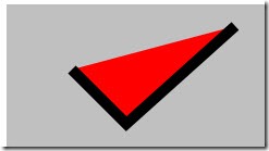
7. 多线段
这个跟Polygon基本一样,只是最后一个点与第一个点不一样,就不会封闭。如:
<Canvas
xmlns="http://schemas.microsoft.com/winfx/2006/xaml/presentation"
xmlns:x="http://schemas.microsoft.com/winfx/2006/xaml">
<Polyline Canvas.Top="10" Canvas.Left="10"
Fill="Red" Stroke="Black" StrokeThickness="10"
Points="50,50 100,100 200,10"/>
</Canvas>
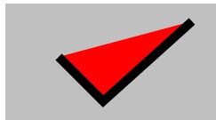
8. 路径(Path)
路径用来表示比较复杂的图形。前面的几种图形它都能表示,同时还可以表示各种复杂曲线图形。
Path主要使用Data属性来表示图形。Data里面指定命令,M表示移动到,L表示画直线到,V表示画垂直线到,
H表示画水平线到,Z表示结束(直接到起始点),C表示三次贝塞尔曲线,Q表示两次贝塞尔曲线,
S表示平滑的贝塞尔曲线,A表示曲线,具体就需要看看帮助文档了。
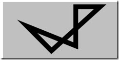
如下,先移动到50,50,再画线到100,100,再画线到200,10,再横向画到150,再纵向画到90,再结束。
<Canvas
xmlns="http://schemas.microsoft.com/winfx/2006/xaml/presentation"
xmlns:x="http://schemas.microsoft.com/winfx/2006/xaml">
<Path Stroke="Black" StrokeThickness="10"
Data="M 50,50 L 100,100 L 200,10 H 150 V 90 Z"/>
</Canvas>

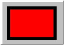
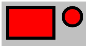
路径中的Data属性还可以设置一些几何形状,如RectangleGeometry, EllipseGeometry, LineGeometry, PathGeometry等等。
如:
<Canvas
xmlns="http://schemas.microsoft.com/winfx/2006/xaml/presentation"
xmlns:x="http://schemas.microsoft.com/winfx/2006/xaml">
<Path Canvas.Top="10" Canvas.Left="10"
Fill="Red" Stroke="Black" StrokeThickness="10">
<Path.Data>
<RectangleGeometry Rect="10,10,150,100" />
</Path.Data>
</Path>
</Canvas>

如果有多个形状,需要放到GeometryGroup中。
<Canvas
xmlns="http://schemas.microsoft.com/winfx/2006/xaml/presentation"
xmlns:x="http://schemas.microsoft.com/winfx/2006/xaml">
<Path Canvas.Top="10" Canvas.Left="10"
Fill="Red" Stroke="Black" StrokeThickness="10">
<Path.Data>
<GeometryGroup>
<RectangleGeometry Rect="10,10,150,100" />
<EllipseGeometry RadiusX="30" RadiusY="30" Center="220, 40" />
</GeometryGroup>
</Path.Data>
</Path>
</Canvas>
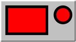
几何形状与上面的图形的区别主要在于几何形状完全是数学描述,不涉及显示相关,也就没有Fill, Stroke之类的属性。
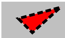
9. 其它几个常用的相关属性
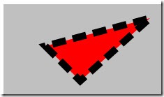
StrokDashArray: 画虚线用。里面放着短线和空格的宽度,如奇数位代表短线,偶数位代表空格。
如:StrokeDashArray=”2,1”, 代表短线为2,空格为1
<Canvas
xmlns="http://schemas.microsoft.com/winfx/2006/xaml/presentation"
xmlns:x="http://schemas.microsoft.com/winfx/2006/xaml">
<Polygon Canvas.Top="10" Canvas.Left="10" StrokeDashArray="2,1"
Fill="Red" Stroke="Black" StrokeThickness="10"
Points="50,50 100,100 200,10"/>
</Canvas>
StrokeLineJoin: 线连接,可以设为Miter, Round, Bevel.
StrokeMiterLimit: 线延伸时的限值。
Visibility: 可视。可以设为Visible或Collapsed. 当设为Collapsed时,不能接收输入事件。
Opacity:透明度。0到1之间的任何值。0表示完全透明。当设为0时,可以接收输入事件。
Stretch: 伸缩。可以设为None,Uniform, UniformToFill。主要是当图形填充为图像,画刷或媒体时用。

相关文章推荐
- WPF and Silverlight 学习笔记(二十七):基本图形的使用(2)Path和位图操作
- WPF and Silverlight 学习笔记(二十六):基本图形使用(1)
- WPF and Silverlight 学习笔记(二十六):基本图形使用(1)
- WPF and Silverlight 学习笔记(二十八):基本图形的使用(3)图形的操作
- WPF and Silverlight 学习笔记(二十七):基本图形的使用(2)Path和位图操作
- WPF and Silverlight 学习笔记(二十八):基本图形的使用(3)图形的操作
- Silverlight学习笔记(九)-----RenderTransform特效【五种基本变换】及【矩阵变换MatrixTransform】
- Silverlight学习笔记基本控件(三)
- Silverlight学习笔记基本控件(四)
- Silverlight学习笔记基本控件(五)
- Silverlight 2学习笔记二:三个基本布局控件(Canvas、StackPanel、Grid )
- Silverlight学习笔记基本控件(六)
- Silverlight学习笔记基本控件(七)
- Silverlight基本控件学习笔记(八)
- 自定义VIEW(学习笔记三)-基本图形的绘制
- Silverlight学习笔记基本控件(一)
- 【基于C++和Python的Opencv3学习笔记之基本图形的绘制】
- SilverLight学习之基本图形
- Open CV 学习笔记:基本图形绘制
- iOS学习笔记-060.图形的基本绘制、图片水印、图片裁剪